


38
Install - Step 7 continued
Power up and cable optional DAEs
Connecting the back-end bus
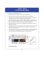
Attach your DAEs in a back-end bus after you have set the enclosure addresses.
Verify that each DAE has a unique bus/enclosure address, and that the first disk
enclosure on each bus (the one that directly connects to the SPE) is EA 0.
1. Connect an HSSDC2-HSSDC2 cable from the expansion (EXP) port on link control
card (LCC) A in DAE EA 0/bus 0 to the primary (PRI) port on LCC A of EA 1.
(LCC A connectors are on the
right
side of the DAE as you face the enclosure rear.)
Make sure to orient the HSSDC2 connectors as shown below. The connector thumb clip faces
up when connecting to LCC B, and down when connecting to LCC A. An audible/tangible
click indicates that the cable is completely seated in the LCC connector.
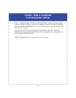
Connecting a disk enclosure to another FC device
2. Continuing on the right (A) side, connect EXP to PRI ports, in sequence, on each
DAE.
•
Make sure not to connect an EXP port to another EXP port, or PRI to PRI.
•
Take care not to connect any A-side ports to LCC B ports.
!
!
!
!
!
EX
P
PR
I
EX
P
PRI
#
!
EXP
PR
I
EX
P
PRI
#
A
B
EMC3244
To Previous Enclosure
PRI
Connector
PRI
PRI
Thumb Clip Up
To Previous Enclosure
PRI
Connector
PRI
PRI
Thumb Clip Down