


Embedded Planet, Inc.
epConnected Vehicle | Product User Manual
Version: 1.0.0 | 25 Feb 22
Embedded Planet, Inc. | 31225 Bainbridge Rd Suite N, Solon, OH 44139 | 216-245-4180 | www.embeddedplanet.com |
Page 22 of 39
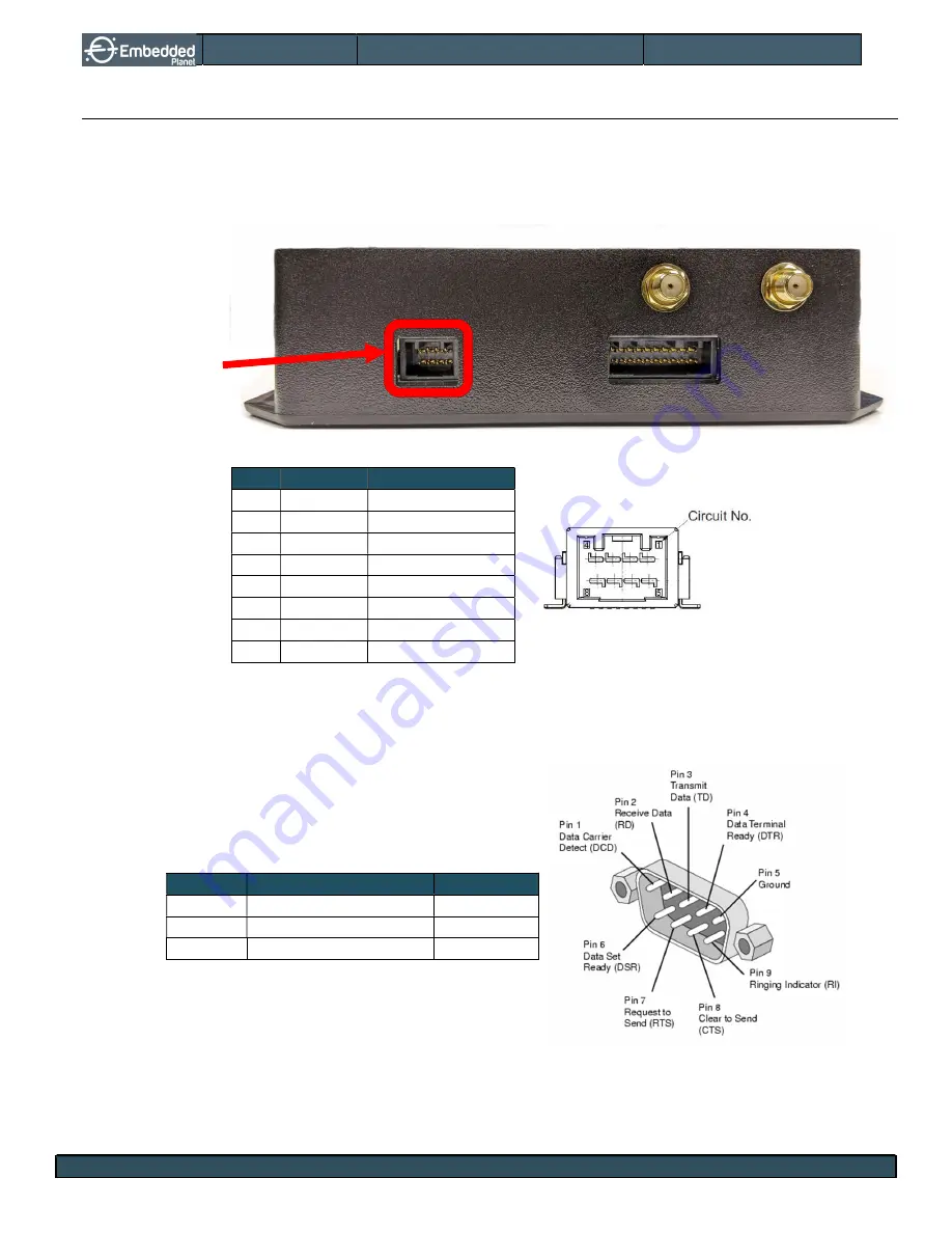
12.4.
Pinouts: Power/CAN Pinout (J5)
The CAN interface on the epConnected Vehicle allows the device to communicate with the vehicle using
an OBDII converter cable. The interface uses a Microchip MCP2515 SPI-to-CAN controller and TI
SN65HVD231 CAN transceiver to manage the CAN bus.
TABLE 13 – POWER/CAN CONNECTOR (J5) PINOUT
Pin Category Description
1
Reference COM
2
CAN
CAN Low
3
RS-232
RS-232 TX IN
4
Power
+12V power input
5
Power
+12V power input
6
CAN
CAN High
7
RS-232
RS-232 RX OUT
8
Reference COM
The OBDII cable for the epConnected Vehicle has three wires that break out a connection to an RS-232
port of a PC, as shown below*.
TABLE 14 – J5 TO DB9 PIN MAP
J5 Pin
Description
DB9 Pin
J5 pin 3
RS-232 TX IN (PC Tx)
DB9 pin 2
J5 pin 7
RS-232 RX OUT (PC Rx)
DB9 pin 3
J5 pin 8
COM (Ground/0V)
DB9 pin 5
*
Virtual RS-232 ports through USB converters like the Tripp Lite: U209-000-R are also supported.
J5: Power/CAN
connector


