


6
7
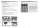
AMPLIFIER MOUNTING
Attention! For your own safety, disconnect the negative battery terminal (GND) or re-
move the main fuse in the positive power cable near the car battery, before you start
any wiring work!
Before you proceed to install this EMPHASER amplifier, it is recommended to map out the
complete system and the respective wiring required. Consider all additional electrical require-
ments and accessories, such as power cables, interconnect cables etc., to complete the install.
Please note that - because of possible interference problems with the existing car electrics
and electronics - especially the routing of the signal cables and the chassis ground connec-
tion will have a profound impact on the trouble-free (noise free!) operation of the amplifier.
The mounting location should be carefully selected and in the interest of passive driver and
passenger safety, the amplifier must be securely mounted. Make sure that there is no wiring
harness, fuel tank etc. behind or below the mounting surface that may be damaged by the
drilling of the holes for the amplifier mounting screws. After installation, there should be a
clearance of at least 5cm to all sides including the top of the amplifier heatsink. Make sure
the unit is not exposed to direct sunlight, humidity, water, oil or spill of other fluids that may
enter the amplifier.
Once the location where the amplifier will be mounted is defined, use the unit as a template
for the marking of the mounting holes with pencil or felt-tip marker. The mounting holes should
be pilot-drilled, using a 2,5mm drill bit. Bolt the amp down.
Important! There must not be a direct contact of the amplifier heatsink, bottom panel
or any other metal part of the amplifier to the vehicle metal panel! Electrical ground-
loops will cause audible hum!
WIRE ROUTING
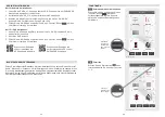
PLUG AND PLAY CABLES
Before you start with the installation, make sure you know the security code of your headunit
(if applicable). Remove the headunit from the dashboard and disconnect the main wire. Find
a place for the EA-D8 and connect the provided (or optionally available car-specific) wire to
the amp. Connect the wire to the headunit. Install the headunit back in the dashboard.
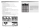
RCA & REMOTE WIRES
You only need to read the following part about RCA and remote wire when you intend to not
use the provided high-level input connector. Do not use high-level and low level RCA inputs
together at the same time.
For best interference free transmission of the music signal, use double or triple shielded RCA
interconnects only. Twisted pair Interconnects offer excellent noise rejection as well. Route
the RCA interconnects away from potential sources of Interference, such as engine comput-
ers, gas pumps, etc.
Carefully run the audio signal interconnects and the remote wire from the head unit or dash-
board to the amplifier. As mentioned before, the audio signal cables should always be routed
completely separate from the power cables. Connect the remote (turn on/turn off) lead to the
respective input terminal of the amplifier and to the remote output of your head-unit. Now you
can connect the RCA interconnects to the respective outputs of your head-unit and to the
inputs of the amplifier. Pay attention to connect the stereo interconnects correspondingly, left
is 1CH and right is always 2CH a.s.o.
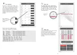
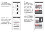
INPUT GAIN ADJUSTMENT EA-D8
To reach a maximum in dynamic response from each individual head-unit/amplifier/speaker
combination, it is important to set the respective input sensitivity controls („GAIN“) of all chan-
nel pairs correctly.
Before you start, you MUST set all tone controls (Bass, Mid, Treble, Loudness etc.) and the
fader on the head unit to their neutral or center positions.
Now turn all input gain controls of the installed amplifiers anti-clockwise to their minimum
positions and start with the channel pair that drives the subwoofer system.
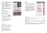
SUBWOOFER CHANNEL(S)
Set the volume control of your head-unit to approximately ¾ of full volume, while playing a
dynamic piece of music. Slowly increase the input gain control of the channel pair driving the
subwoofer(s), by turning the GAIN control clockwise. Increase clockwise until the bass starts
to distort. Reduce the main volume level of your head-unit to a medium listening level. Proceed
with further channels, if applicable.
SATELLITE CHANNELS
Slowly increase the input gain control of the channel pair driving the satellite system, by turning
the GAIN control clockwise. Increase clockwise until you reach a good tonal balance with a
slight emphasis of the bass range. Repeat for all further channels.
FINE TUNING OF ALL CROSSOVER FREQUNCY POINT SETTINGS
Finally you can attempt to fine-tune the H.P.F. and/or the L.P.F. crossover frequencies on your
amplifier setup, to reach the maximum tonal balance and channel integration of all loudspeak-
ers connected to your car audio system.