


3
Table of contents
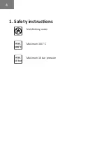
1. Safety instructions
4
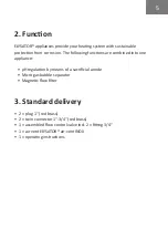
2. Function
5
3. Standard delivery
5
4. Specification
4.1. Appliance description
6
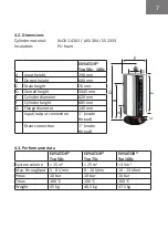
4.2. Dimensions
7
4.3. Performance data
7
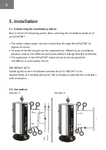
5. Installation
5.1. Determining the installation position
8
5.2. Connection
8
6. Commissioning
6.1. Filling/venting
9
6.2. Setting the throughput
9
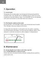
7. Operation
7.1. System water
10
7.2. Checking the condition of the anodes
10
8. Maintenance
8.1. Interpreting the indicator and actions required
10
8.2. Sludge removal
12
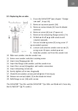
8.3. Replacing the anodes
13
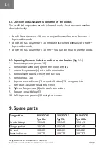
8.4. Checking and assessing the condition of the anodes
14
8.5. Replacing the wear indicator and the control button
14
9. Spare parts
14
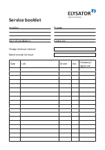
Service booklet
16