User’s manual r.0805 EQ45 (EN)
www.elyq.com
Page 9/21
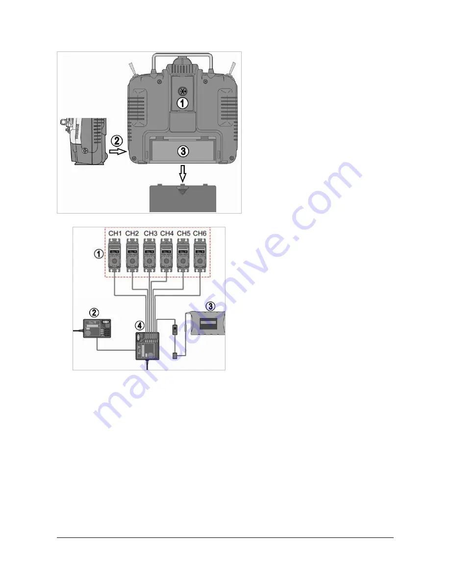
Transmitter back and side view
In the back side of the transmitter, there are the
following plugs:
1.
Serial Comm Port
: plug the
communication cable in order to configure
the transmitter.
2.
Charger Port
: use to charge the
transmitter batteries. ElyQ doesn’t provide
any battery charger and recommends to
unplug the batteries and than charge
externally.
3. Battery
placeholder
Receiver and Servo connectivity
The radio supports six channels. In the figure in the
right, there is a simple connection diagram:
1.
Helicopter servos
2.
Receiver module
3.
Battery
4.
Main Receiver Module
: in order to
increase the radio receiving field, it is
necessary that the two receiver antennas
form an angle of 90 degrees.
Transmitter matching code
This is 2.4GHz Frequency model product makes an automatic address code. It uses digital transmission mode to
prevent outside interference (active and/or passive). Our products are pre-paired: you do not need to match them by
yourself. If it is necessary to match the receiver with another transmitter, please follow the next instructions:
1. Install the battery to 2.4 GHz transmitter and shut it down. Insert the matching line into the BAT channel of the
receiver.
2. Connect the receiver battery to any one of the channel port. The two LEDs start flashing meaning that the
receivers are going to the matching status.
3. Press and hold the button on the transmitter, and then switch on the power supply.
4. Check the LED on the receiver: if it is not flashing anymore, the matching process has finished successfully
(the delay should be about 10s).
5. Release the matching key on the transmitter, and then disconnect the receiver batteries and the matching line.
6. Install the servos and then test the helicopter.
7. If the tests fail, please repeat the actions above.
8. If the tests succeed, insert the power supply port into BAT, match complete (the above ways of match is only
suitable on ElyQ 2.4G products).


