


5
5.3 HOW TO BUILD AIR DUCT
(AIR DISTRIBUTION AND RETURN)
5.3.1 Cold Air Distribution
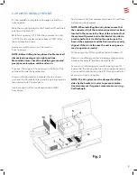
A cold air duct with a diameter of 2.5 inch and at least
one outlet must be connected to all three cold air
outlets of the unit (7, 8, 9).
Insert the cold air ducts into the cold air outlets of
the unit and route to the air outlet nozzles. Ensure that
the cold air ducts are securely seated in the cold
air outlets.
NOTES!
The cold air distribution is designed individually
using the modular principle for different vehicle
model; A wide range of accessories is available for
this purpose.
For the sake of achieving the best cooling power we
recommend:
– Route cold air ducts to air outlet nozzles as short and
straight as possible.
– The total length of cold air duct shouldn’t be longer
than 50 feet.
– Connect the longest cold air duct (max. 27 feet) to
the central cold air outlet (8), since it has the highest
air capacity
– In order to avoid condensation, do not route the cold
air ducts close by inflowing outside air (or behind
the refrigerator).
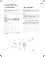
5.3.2 Circulated Air Return
The circulated air is drawn in again by the unit, either
via an additional rectangular air grille or via several
small openings (e. g. in the stowage box wall) with a
total area of at least 50 sq.in
NOTE!
The flue from the vehicle interior to the AC unit instal-
lation area must be getting close to the equipment to
supply optimum air exchange. Covers must be fitted
if necessary to prevent the circulated air return from
being affected by stowed objects.
5.4 HOW TO INSTAL THE WALL PAD
The wall pad (12) should preferably be mounted to
the wardrobe in such a way that the remote control
can be pointed at it without obstructions (length of
connecting cable Max 16 feet).
Take apart wall pad to cover frame (12) and back
frame (13). Drill
Æ
1.6 inch hole. Lead wall pad cable
(15) through hole towards the back and instal wall pad
with 2 screws (14 – not included in scope of delivery).
Then fit cover frame (12) and route cable (15) to AC
control board.
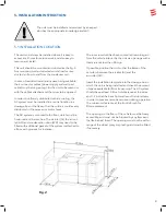
Fig 4


