background image

www.prolight.co.uk

Fury 200 DTW 2 Cell Blinder


User Manual

10

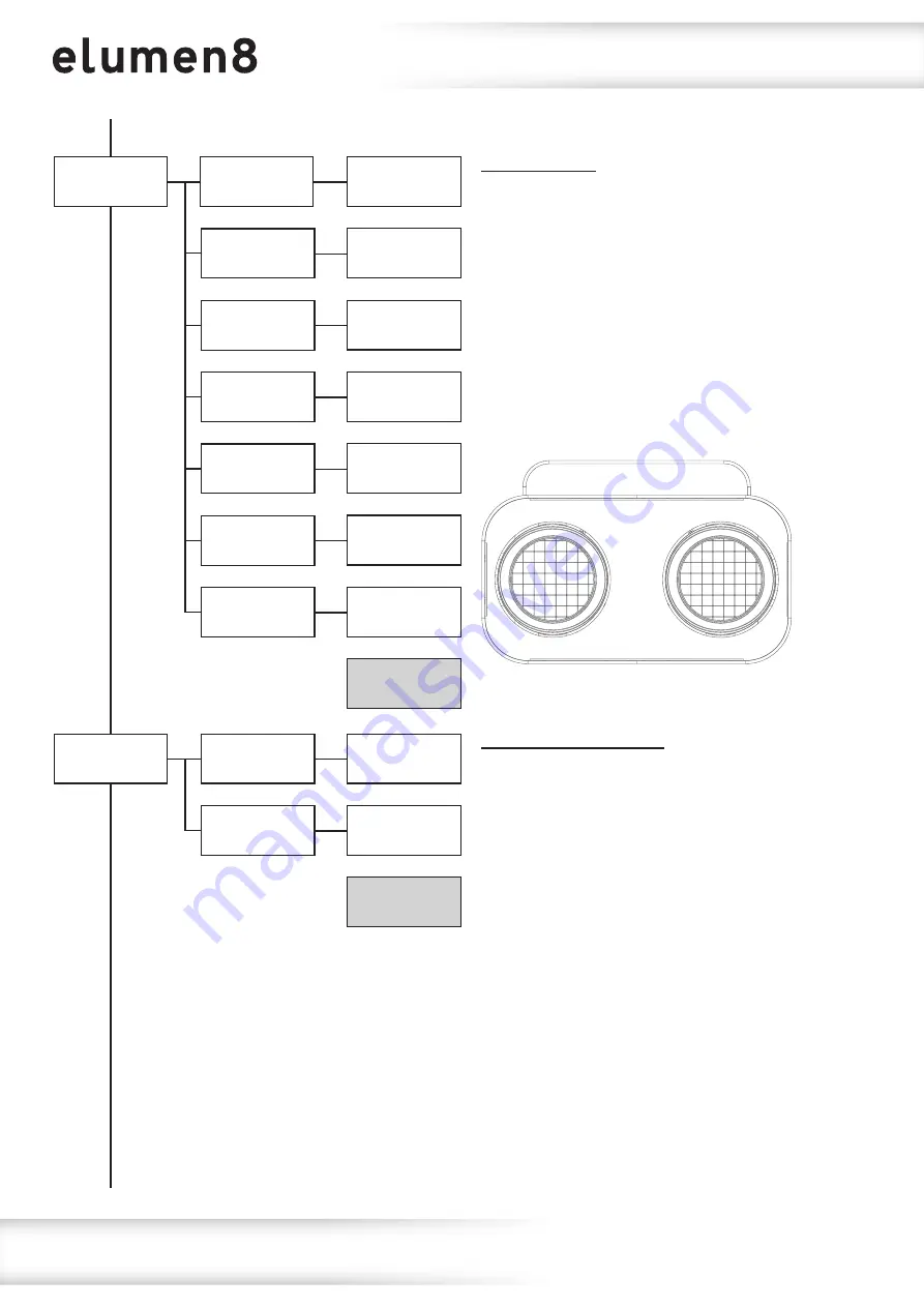
5: Dimmer

1) White 1

White 1 

xxx

Default 

000

B Ring

xxx

G Ring

xxx

R Ring

xxx

Amber 2 

xxx

White 2 

xxx

Amber 1 

xxx

2) Amber 1

3) White 2

4) Amber 2

5) R Ring

6) G Ring

7) B Ring

Operating instructions

Manual mode:

To access the manual dimming mode, press the 

“MODE”

 button until 

“5: Dimmer”

 is highlighted 

on the OLED display. Press the 

“SET”

 button 

and use the 

“UP”

 and 

“DOWN”

 buttons to select 

between White Pods 1-2, Amber Pods 1-2, 
Backlight R, Backlight G or Backlight B.  
Press the 

“SET”

 button and use the 

“UP”

 and 

“DOWN”

 buttons to adjust the brightness 

between 000-255.  
Press the 

“SET”

 button to confirm the setting.

1

2

6: Halogen

1) Halogen 1

Halogen 1 

xxx

Halogen 2 

xxx

2) Halogen 1

Default 

000

Manual halogen mode:

To access the manual halogen dimming mode, 
press the 

“MODE”

 button until 

“6: Halogen”

 is 

highlighted on the OLED display. Press the 

“SET”


button and use the 

“UP”

 and 

“DOWN”

 buttons to 

select between Pods 1-2. Press the 

“SET”

 button 

and use the 

“UP”

 and 

“DOWN”

 buttons to adjust 

the brightness between 000-255.  
Press the 

“SET”

 button to confirm the setting.

Содержание ELUM430

Страница 1: ...Order codes ELUM430 Fury 200 DTW 2 Cell Blinder User Manual ...

Страница 2: ...is will reduce the system s life Only use the equipment indoors Do not expose to flammable sources liquids or gases Always disconnect the power from the mains when equipment is not in use or before cleaning Only handle the power cable by the plug Never pull out the plug by pulling the power cable Make sure that the available mains supply voltage is between 100 240V AC 50 60Hz Make sure that the po...

Страница 3: ... button menu with OLED display PowerCON TRUE1 input output IP rated 5 Pin XLR input output Fan cooled Fury 200 DTW 2 Cell Blinder Specifications Fury 200 DTW Power consumption 198W Power supply 100 240V 50 60Hz Fuse F5A 250V IP rating IP65 Dimensions 275 x 398 x 215mm Weight 7 2kg Order code ELUM430 0m 1m 2m 3m 4m 5m 50 Lux 17528 4382 1947 50 1095 701 The Fury IP65 rated blinders are loaded with 9...

Страница 4: ... 100 240V 50 60Hz DMX INPUT DMX OUTPUT www prolight co uk POWER CONSUMPTION 198W Fury 200 DTW Blinder 06 05 01 02 03 04 Fuse The Fury 200 Blinder is fitted with an internal mains line fuse The fuse must only be changed by qualified personnel Before opening the fixtures housing or changing the fuse the fixture must be disconnected and isolated from the mains supply When closing the fixture please e...

Страница 5: ...oad limits the material being used at the installation area and periodic safety inspections of the fixture and installation material If you do not have the relevant experience and or qualifications please do not attempt the installation yourself The installation should be checked annually by a qualified person The eLumen8 Fury 200 can be operated in a number of mounting positions as shown in the d...

Страница 6: ...lation 1 Fasten the clamp to the fixtures bracket 2 Mount the fixture onto your truss system via the clamps and tighten to ensure secure 3 Pull the safety cable through the safety cable holes located on the metal base plate on the underside of the fixture and around the truss 1 2 3 ...

Страница 7: ...then return to its home screen Pressing the MODE button once will take the user to the fixtures main menu Using the UP and DOWN buttons you can then navigate between the different options in the main menu Pressing the SET button on one of these options allows you to access the sub menu where you can use the UP and DOWN buttons to select option value required Once the option value has been selected...

Страница 8: ...o highlight 2 Colour Press the SET button and use the UP and DOWN buttons to select the colour required between 01 19 Press the SET button to confirm the setting If program mode 02 23 is selected use the UP and DOWN buttons to highlight 2 Speed Press the SET button and use the UP and DOWN buttons to select the speed required between 001 100 Press the SET button to confirm the setting Now use the U...

Страница 9: ...l 4 Slave is highlighted on the OLED display Press the SET button and use the UP and DOWN buttons to select between Yes and No Press the SET button to enter slave mode when yes is selected Main Menu Defaults are in grey DMX channel To access DMX channel mode press the MODE button until 3 DMX is highlighted on the OLED display Press the SET button and use the UP and DOWN buttons to highlight 2 Chan...

Страница 10: ...een White Pods 1 2 Amber Pods 1 2 Backlight R Backlight G or Backlight B Press the SET button and use the UP and DOWN buttons to adjust the brightness between 000 255 Press the SET button to confirm the setting 1 2 6 Halogen 1 Halogen 1 Halogen 1 xxx Halogen 2 xxx 2 Halogen 1 Default 000 Manual halogen mode To access the manual halogen dimming mode press the MODE button until 6 Halogen is highligh...

Страница 11: ...access the dimming speed setting press the MODE button until 7 Settings is highlighted on the OLED display Press the SET button and use the UP and DOWN buttons to select 2 Dimmer Speed Press the SET button and use the UP and DOWN buttons to select between Fast LED or Smooth Halogen Press the SET button to confirm the setting 3 Dmx Fail 1 Blackout 2 Hold 3 Auto 4 Program DMX fail setting Sets what ...

Страница 12: ...isplay lock setting press the MODE button until 7 Settings is highlighted on the OLED display Press the SET button and use the UP and DOWN buttons to select 5 Lock Press the SET button and use the UP and DOWN buttons to select between On and Off Press the SET button to enable Display Lock when yes is selected Please note After 30 seconds of inactivity the display will lock To unlock the menu hold ...

Страница 13: ...isplays the fixtures version each pods temperature and RDM ID To display the fixture information press the MODE button until 8 Information is highlighted on the OLED display Press the SET button and the fixtures version each pods temperature and RDM ID will be displayed 8 Information Versions xx C xx C UID ...

Страница 14: ...mmer 0 100 CH5 000 255 Blue backlight dimmer 0 100 7 channel mode Channel Value Function CH1 000 255 Halogen master dimmer 0 100 CH2 000 255 Pod 1 halogen dimmer 0 100 CH3 000 255 Pod 2 halogen dimmer 0 100 CH4 000 255 Backlight master dimmer 0 100 CH5 000 255 Red backlight dimmer 0 100 CH6 000 255 Green backlight dimmer 0 100 CH7 000 255 Blue backlight dimmer 0 100 1 2 10 A channel mode Channel V...

Страница 15: ...Pod 2 green backlight dimmer 0 100 CH10 000 255 Pod 2 blue backlight dimmer 0 100 13 channel mode Channel Value Function CH1 000 255 Master dimmer 0 100 CH2 000 010 No function 011 255 Strobe slow fast CH3 000 255 Pod 1 warm white dimmer 0 100 CH4 000 255 Pod 1 amber dimmer 0 100 CH5 000 255 Pod 2 warm white dimmer 0 100 CH6 000 255 Pod 2 amber dimmer 0 100 CH7 000 255 Backlight master dimmer 0 10...

Страница 16: ...ilac 232 244 All pods Dark Yellow 245 255 All pods White RGB CH5 000 015 No function 016 030 Program 2 031 045 Program 3 046 060 Program 4 061 075 Program 5 076 090 Program 6 091 105 Program 7 106 120 Program 8 121 135 Program 9 Channel Value Function CH5 cont 136 150 Program 10 151 165 Program 11 166 180 Program 12 181 195 Program 13 196 210 Program 14 211 225 Program 15 226 240 Program 16 241 25...

Страница 17: ...lowing all makes and models of different manufactures to be linked together and operate from a single controller as long as all fixtures and the controller are DMX compliant To ensure proper DMX data transmission when using several DMX fixtures try to use the shortest cable path possible The order in which fixtures are connected in a DMX line does not influence the DMX addressing For example a fix...

Страница 18: ...ne a cable adaptor must be used The diagram below details the correct cable conversion 5 pin XLR female Pin 1 GND screen Pin 2 Signal Pin 3 Signal Pin 4 N C Pin 5 N C 3 pin XLR female Pin 1 GND screen Pin 2 Signal Pin 3 Signal 3 pin XLR male Pin 1 GND screen Pin 2 Signal Pin 3 Signal 5 pin XLR male Pin 1 GND screen Pin 2 Signal Pin 3 Signal Pin 4 N C Pin 5 N C DMX setup Termination reduces signal ...

Страница 19: ...onnected a new power run will need to be started Please note Caution should be used when power linking other fixtures to the Fury 200 as the power consumption of other fixtures will vary Fixtures fitted with lamps often require 2 3 times more current on startup these may require their own power source POWER OUTPUT 100 240V 50 60Hz POWER INPUT 100 240V 50 60Hz DMX INPUT DMX OUTPUT www prolight co u...

Страница 20: ...ent possible harm to the environment or human health from uncontrolled waste disposal please separate this from other types of wastes and recycle it responsibly to promote the sustainable reuse of material resources Household users should contact either the retailer where they purchased this product or their local government office for details of where and how they can take this item for environme...

Страница 21: ...www prolight co uk Fury 200 DTW 2 Cell Blinder User Manual 21 ...

Страница 22: ...www prolight co uk Fury 200 DTW 2 Cell Blinder User Manual 22 ...

Страница 23: ...www prolight co uk Fury 200 DTW 2 Cell Blinder User Manual 23 ...

Страница 24: ...www prolight co uk Fury 200 DTW 2 Cell Blinder User Manual 24 ...

Отзывы: