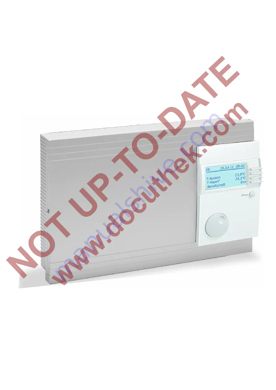
Installation and Operating Manual Merlin 5064 V3
System Manager
Please observe the safety instructions and read through this manual carefully before commissioning the equipment.
Страница 1: ...Installation and Operating Manual Merlin 5064 V3 System Manager Please observe the safety instructions and read through this manual carefully before commissioning the equipment ...
Страница 2: ...scribes the maximum version of the controller meaning that not all statements are relevant for your device The hydraulic diagrams contained in these operating and installation instructions are schematic diagrams They are designed to assist you in selecting the correct program and in no way describe or replace system planning according to good professional practice for this reason it cannot be guar...
Страница 3: ...ater temperature F11 F5 10 T Flow Flow temperature F11 F5 10 Need Opti Time last required heating up time 10 Solar MF Solar Multifunction 10 T MF 1 4 F11 F14 10 T Solar 1 2 collector temperature 10 Sol pump 1 2 3 collector pump status 10 Charge ST DHW BU 3 status of Cylinder charging pump 10 Charge DHW2 BU2 status of transfer pump 10 User Area 11 Installation 11 English Language 11 LCD Contrast 11...
Страница 4: ...imum temperature of the boiler 24 Dyn Upward dyn heat generator connection K 24 Dyn Downward dynamic heat generator deactivation K 24 Reset Time reset time for I Control 24 Modulation Max 24 Modulation Min 24 Min Mod HS 24 Modulat DHW only for HW modules 24 Sequence 1 24 Sequence 2 24 Sequ Change type of sequence change 24 Time Seq Mod time to sequence change 24 Block Time delay time for next stag...
Страница 5: ...Terminal assignment 46 Installation 07 Merlin 1144 Mixer valve extension 47 Terminal assignment 47 Installation 09 Cooling function in heating circuit return 48 Terminal assignment 48 Installation 10 Central cooling function and solar integration 49 Terminal assignment 49 Solar installations examples 50 Accessories 51 The operating module Merlin BM BM 8 and Lago FB 51 Remote control FBR2 51 Teleph...
Страница 6: ... place with the rotary knob F button Adjust Favorites or additional displays Line 3 Display the temperature of the heat generator 1 or the collector for cascades F button Display of the set temperature for the HS Line 4 Left Display of the central operating mode Right Display of the current situation of the first heating circuit provided it is not remote controlled Heating Reducing Party or Holida...
Страница 7: ... program 2 HW according to HW program F Summer Summer mode Heating OFF HW according to HW program h Heating Day mode 24 h heating with comfort temperature 1 HW according to HW program C Reducing Night mode 24 h heating with reduced temperature HW according to HW program W Service automatic reset after 15min The heat generator regulates to the maximum heat generator temperature When the heat genera...
Страница 8: ...esired 1 20 0 C When applying voltage the level installation is displayed once only Once the values grouped here have been set the controller is operable When the level appears later on e g after a power outage the function can just be ended Areas Type of set values Display System value display e g sensor values and setpoints No adjustments can be made Incorrect operation is therefore impossible i...
Страница 9: ...irculation pump On Off Installation T Outside F9 The measured outside temperature is smoothed for control purposes The smoothed value is displayed here Ext setpoint F15 The 0 10V input can be used to preset an accumulative set value for the control system see V CURVE p 26 T Header only for Cascades F8 The set value appears after the F button is pressed The set value corresponds to the maximum requ...
Страница 10: ...orage tank F15 cascade Heatcircuit 1 2 T Room room temperature F2 F15 Only if a sensor or a FBR is connected T Pool pool temperature F2 F15 Only if the heating circuit is configured as pool controller T DHW hot water temperature F11 F5 Only if the heating circuit is configured as hot water circuit T Flow Flow temperature F11 F5 Display of the measured flow temperature of the heating circuit only f...
Страница 11: ...showering outside hot water times Charging starts when the temperature falls below T DHW 1 des by the switching hysteresis T DHW des 1 3 Hot water temperature setting Required hot water temperature setting T DHW 1 des used in first enable time T DHW 2 des used in second enable time T DHW 3 des used in third enable time of hot water program BoB Value Operation Without Burner Energy saving function ...
Страница 12: ...n the temperature drops 1K below If starting conditions are set for room as well as outside temperature both conditions must be met before cooling operation starts T Limit Day T Limit Night Only valid if the function is activated Set value Expert Heating circuit Pump function heating limits Pump switching according to heating limit If the outside temperature that is measured and calculated by the ...
Страница 13: ...perature fluctuations OFF pure weather dependent control 0 pure weather dependent control 20 pure room temperature control Special function with room influence 0 For one off heating requirements during the night reduction the heating pump continues to run until the next heating period is reached see chapter entitled Circulation pump control T Room adj Room sensor adaptation In the case of room con...
Страница 14: ...ng time 2 Heating time 3 Mo Tu We Th Fr Sa Su Press the F button Time Program Use to search for the desired time program e g Heatcircuit 2 Prog2 Use the F button here button 3 to select time program Heatcircuit 2 Prog2 Monday Use to search for weekday block e g Mo Fr Monday Friday Use the F button OK to select a block 06 00 08 00 16 00 22 00 Use the F button OK to select a time 06 00 08 00 16 00 2...
Страница 15: ...stalled in the system the time is blanked out on all the other controllers in the system A max of one Time Master can be set on the BUS Date Please first set the year and then the month Then the number of days of the month are calculated during the setting Holiday function Please do not enter the day of travel as the start date but the first day of the holiday no more heating from this day Please ...
Страница 16: ...e Sensor 09 Outside temperature Sensor 11 Flow temperature heatcircuit 1 temperature multifunction 1 Sensor 12 Hot water temperature lower or temperature multifunction 2 Sensor 13 Solid fuel HS temperature or collector 2 or temperature multifunction 3 Sensor 14 Collector 1 temperature or temperature 4 Sensor 15 Light 0 10V Room temperature heatcircuit 2 or measured value of the light sensor or vol...
Страница 17: ... activated by means of presetting an output value 50 After closing the service functions the entries are reset automatically Burner time and Burner starts For example select Burner time F button Shows the current values Reset display Use the F button to select the boiler and the level Use the F button to Reset Use the F button End to exit the level STL test Start the STL test F button Use to searc...
Страница 18: ...n system Off no time master each heating circuit has its own time On controller is time master all controllers and remote controls take over the time settings of this controller No more than 1 Time Master is permitted in the system Plant Select selecting basic controller functions This set value can be used to preset the other values of the start up level see also installation description on page ...
Страница 19: ... buffer HWactual 5K Hysteresis HW charge pump OFF Upper buffer HWactual 02 Combination storage tank for heating and HW operation HS1 is activated with reference to sensor buffer middle F2 DHW Relief operates on boiler sensor BS HW charge pump ON BS HWactual 5K Hysteresis HW charge pump OFF BS HWactual 03 passive buffer storage for heating operation F1 F3 The buffer will not load by the conventiona...
Страница 20: ...on zone The circulation pumps are switched off and the mixers are shut until the boiler has reached the start up temperature Min Delimi minimum delimiter HS Not in cascade operation Decreased condensation build up in HS with low heat requirements Switching the HS off is always done earlier when achieving the HS minimum temperature Min T HS1 Hysteresis 5K 00 Minimum delimiter for heat curve The HS ...
Страница 21: ...n switch off point Max T HS Max reduce Dyn cutoff Load sensitive premature deactivation of the HS by the gradient of the temperature increase K min When the HS is operating without load the gradient value is high When the HS reaches or exceeds the gradient set here the HS is switched off at the earliest dynamic switch off point Max T HS Max reduce If the temperature increase is less the switch off...
Страница 22: ...sing gradient procedure takes effect when heat consumption is high slow HS temperature increase D T HS Cool When the HS reaches this temperature the emergency cooling function via the consumer circuits is activated This switching patterns is also effective for operating two switching heat generators via the burner relays A6 and A7 Switch on the 1st Burner stage when temperature drops below set tem...
Страница 23: ...BUS or connected Locally HS1 relay 6 An X on the display indicates that a heat source has responded on the BUS Capacity Stage heat generator output for each stage Display of the HS number and the stage Selection with Prog button Input Adjustment of HS output Stage HS not available 0 Stage available and deactivated In the case of heat generators with the same output a boiler release is sufficient e...
Страница 24: ...ion Min If values drop below this modulation degree the last heat generator of the current sequence is switched off Min Mod HS Connection of the next heat generator will only occur if the resulting modulation degree for the different heat generators then exceeds the value set here For optimum operation with maximum number of burners Set Modulation Max 0 and Modulation Min to the minimum modulation...
Страница 25: ...rator deactivation K Small value fast deactivation Large value slow deactivation E Values set to high can lead to overheating of the HS and triggering the STB Calculation Reaches the summed rule difference in Kelvin the adjusted value thus this causes the disconnection of all HS Set values for buffer storage T Buffer Charge Temperature to which the buffer storage must be charged at the sensor sens...
Страница 26: ...odulation depth via the 0 10V input 0 10V I O Designation Value range Standard IV V CURVE 00 11 00 CURVE 11 U1 0 00V 10 00V 4 00V CURVE 11 U2 0 00V 10 00V 0 10V CURVE 11 T1 00 C 120 C 20 C CURVE 11 T2 00 C 120 C 90 C Curve 11 UO 0 00V 10 00V 5 00V Use the F button End to exit the level Table of voltage curves that can be chosen No U1 U2 T1 T2 UO 0 2 0 10 0 0 90 2 0 1 2 5 0 3 38 80 5 0 2 2 5 0 3 38...
Страница 27: ...eed drying process The screed program can be used for function heating in accordance with DIN EN 1264 4 and for heating freshly laid screed ready for flooring Screed drying can only be carried out for mixer circuits After starting the program runs through the set flow temperatures The integrated mixer circuits control to the set flow temperature The boiler provides this temperature irrespective of...
Страница 28: ...iler temperature drops below the temperature maximum flow temperature 5K T HS DHW increase during HW operation Heat generator setting with hot water preparation hot water temperature setting T HS DHW The boiler must be run at a higher temperature during hot water preparation so that the hot water temperature in the storage tank can be reached via the heat exchanger Hysteresis DHW hot water hystere...
Страница 29: ...r temperature set value can be entered in the user area of the associated heating circuit level T DHW 1 2 3 The heating program for the heating circuit acts as an enable program for the storage tank The storage tank set value is set to 10 C during the reduction period The boiler controller hot water priority function can be used partial priority acts like priority Return flow Return flow temperatu...
Страница 30: ...tallation cooling mode In the Cooling operating mode this temperature is adjusted via the mixer in the heating circuit flow OFF Heating circuit is not cooled Mixer Close Pump Off CLOSE Mixer as bypass valve Mixer Close Pump On T Frost protect frost protection temperature If the outside temperature drops below the programmed value the system switches to frost protection mode pumps are switched on F...
Страница 31: ...ON When heat is requested by a consumer OFF Without consumer heat request If at least one consumer in the system requests heat the pump is switched on The after run function runs after the burner has been switched on 02 Circulation time Switching the relay according to the time program for the circulation pump 03 Booster pump ON When heat is requested by an internal consumer OFF When no heat is re...
Страница 32: ... this function can be used to charge the storage tank from a heat exchanger without PT 1000 sensor T SOLAR Temperature of the solar panel T B Temperature of active storage tank at inlet area ON T SOLAR T B MF HYST OFF T SOLAR T B MF HYST OFF The pump is switched on when the temperature of the solar panel exceeds the temperature of the active storage tank see switch over valves in the infeed area b...
Страница 33: ...ways measured at the MF4 sensor T MF4 Exception In the case of function 23 at MF4 the sensor assigned to the MF relay Cylinder charging pump 3 is used to determine the temperature of the medium used for charging the storage tank T SOLAR T SOLAR T MF4 Temperature of the solar collector T SOLAR T MF 1 3 Temperature of the heat exchanger T Storage 3 F15 temperature of storage tank 3 in the infeed are...
Страница 34: ...fed the storage tanks during the day to temperatures in excess of the set maximum storage tank temperatures then the storage tank can automatically be cooled at night between 1 00 and 6 00 hours by activating this function by switching on the feeding pumps to the set maximum temperature of the storage tank The storage tank cannot be fed during this period Recooling can take place only when the tem...
Страница 35: ...frost protection temperature setting Boiler frost protection The boiler frost protection is activated when the boiler temperature drops below 5 C The boiler is switched on until the boiler temperature exceeds the Min T HS1 Flow or storage tank sensor frost protection The sensor frost protection is activated when the flow or storage tank temperature drops below 7 C Only the relevant pump is switche...
Страница 36: ...e can be activated using the operating mode selector switch Hot water loading is only possible by means of the conventional heat generators If a bypass valve for cooling operation MF is activated the bypass valve is switched in the Cooling operational mode The refrigerating machines and associated HS pumps are switched on when required by the heating circuits until the return flow temperature has ...
Страница 37: ...roller Before removing the controller it must be ensured that the controller is completely voltage free disconnect it from the network Only replacement of electronics 1 Remove the controller by pulling on the right side then open the controller cover E For a fixed controller Open the cover of the controller housing and loosen the fastening screws on the back Then remove the controller on the right...
Страница 38: ...s with the mechanical boiler thermostat if present E Attention Bus lines and sensor lines are to be installed separately from supply lines After connecting or modifying the connections of sensors and remote controls the controller must be briefly switched off mains switch fuse The function of the controller is reconfigured in accordance with the connected sensors the next time the controller is sw...
Страница 39: ...collector 2 Sensor multifunction 3 11 F14 PT 1000 Solar collector 1 Sensor multifunction 4 12 F15 FBR Terminal 1 Room sensor HC2 0 10V input storage tank 3 13 F17 FBR Terminal 3 Room set value Telephone switch HC2 Return flow sensor refrigeration machine 14 eBUS Combustion machine DCF 0 10V for heat generator 15 eBUS Combustion machine DCF 0 10V for heat generator 16 H CAN BUS High data line 17 L ...
Страница 40: ...lay sensor 4 PT1000 but not if circulation time applies 12 F15 optional room sensor for Heatcircuit 2 12 13 FBR optional FBR2 FBR1 for Heatcircuit 2 14 15 eBUS to the heat sources FA DCF 16 17 Data line CAN BUS 18 19 Power supply CAN BUS Alternatively Isolating circuit for hot water preparation Mains Ax N 20 N conductor mains 21 Power supply unit 24 A1 Pump Heatcircuit 1 25 A2 Pump Heatcircuit 2 2...
Страница 41: ...if circulation time applies 12 F15 optional room sensor for Heatcircuit 2 12 13 FBR optional FBR2 FBR1 for Heatcircuit 2 14 15 eBUS to the heat sources FA DCF only with heat sources via eBUS 16 17 Data line CAN BUS 18 19 Power supply CAN BUS Alternatively Isolating circuit for hot water preparation Mains Ax N 20 N conductor mains 21 Power supply unit 24 A1 Pump Heatcircuit 1 25 A2 Pump Heatcircuit...
Страница 42: ...header pump 11 F14 optional Multifunction relay sensor 4 PT1000 but not if circulation time applies 12 F15 optional room sensor for Heatcircuit 2 12 13 FBR optional FBR2 FBR1 for Heatcircuit 2 14 15 0 10V Output to boiler 16 17 Data line CAN BUS 18 19 Power supply CAN BUS Mains Ax N 20 N conductor mains 21 Power supply unit 24 A1 Pump Heatcircuit 1 25 A2 Pump Heatcircuit 2 26 A3 Cylinder charging ...
Страница 43: ...ater tank lower 10 F13 optional Multifunction relay sensor 3 PT1000 but not for header pump 11 F14 optional Multifunction relay sensor 4 PT1000 but not if circulation time applies 12 F15 optional room sensor for Heatcircuit 2 12 13 FBR optional FBR2 FBR1 for Heatcircuit 2 14 15 optional eBUS DCF 16 17 Data line CAN BUS 18 19 Power supply CAN BUS Mains Ax N 20 N conductor mains 21 Power supply unit...
Страница 44: ...t water tank lower 10 11 12 F15 optional room sensor for Heatcircuit 2 12 13 FBR optional FBR2 FBR1 for Heatcircuit 2 14 15 optional eBUS DCF 16 17 Data line CAN BUS 18 19 Power supply CAN BUS Mains Ax N 20 N conductor mains 21 Power supply unit 24 A1 Pump Heatcircuit 1 25 A2 Pump Heatcircuit 2 26 A3 Cylinder charging pump 27 A4 Mixing Valve Heatcircuit 2 open 28 A5 Mixing Valve Heatcircuit 2 clos...
Страница 45: ...orage tank sensor Middle 7 F1 Buffer storage tank sensor Lower 8 F11 Flow sensor Heatcircuit 1 9 F12 optional hot water tank lower 10 F13 Solid fuel boiler sensor HS2 PT1000 11 F14 optional Sol Panel PT1000 12 F15 optional room sensor for Heatcircuit 2 12 13 FBR optional FBR2 FBR1 for Heatcircuit 2 14 15 optional eBUS DCF 16 17 Data line CAN BUS 18 19 Power supply CAN BUS Mains Ax N 20 N conductor...
Страница 46: ...ler 5 F3 Buffer storage tank sensor Top 6 F2 Buffer storage tank sensor Middle 7 F1 Buffer storage tank sensor Lower 8 F11 Flow sensor Heatcircuit 1 9 10 F13 Solid fuel boiler sensor HS2 PT1000 11 F14 Sensor Solar Panel PT1000 12 F15 optional room sensor for Heatcircuit 2 12 13 FBR optional FBR2 FBR1 for Heatcircuit 2 14 15 optional eBUS DCF 16 17 Data line CAN BUS 18 19 Power supply CAN BUS Mains...
Страница 47: ...sor Heatcircuit 1 9 10 11 12 F15 optional room sensor for Heatcircuit 2 12 13 FBR optional FBR2 FBR1 for Heatcircuit 2 14 15 16 17 Data line CAN BUS 18 19 Power supply CAN BUS Mains Ax N 20 N conductor mains 21 Power supply unit 24 A1 Pump Heatcircuit 1 25 A2 Pump Heatcircuit 2 26 27 A4 Mixing Valve Heatcircuit 2 open 28 A5 Mixing Valve Heatcircuit 2 closed 29 30 32 33 34 A8 Mixing Valve Heatcircu...
Страница 48: ...atcircuit 1 6 F2 optional room sensor for Heatcircuit 1 7 8 9 F12 optional hot water tank lower 10 11 F14 optional Multifunction relay sensor 4 PT1000 e g solar panel sensor 12 13 F17 Return flow sensor refrigerating machine 14 15 optional eBUS DCF 16 17 Data line CAN BUS 18 19 Power supply CAN BUS Mains Ax N 20 N conductor mains 21 Power supply unit 24 A1 Pump Heatcircuit 1 25 A2 Pump Heatcircuit...
Страница 49: ...Panel PT1000 12 F15 optional room sensor for Heatcircuit 2 13 F17 Return flow sensor refrigeration machines 14 15 optional eBUS DCF 16 17 Data line CAN BUS 18 19 Power supply CAN BUS Mains Ax N 20 N conductor mains 21 Power supply unit 24 A1 Pump Heatcircuit 1 25 A2 Pump Heatcircuit 2 26 A3 Cylinder charging pump 27 A4 Mixing Valve Heatcircuit 2 open 28 A5 Mixing Valve Heatcircuit 2 closed 29 30 A...
Страница 50: ... charging pump 27 28 29 provided a corresponding hydraulic system is also installed all storage tanks are connected to the collector in parallel by means of charging pumps To comply with the hydraulic system shown a collector pump 23 is programmed to MF4 Switching between the different storage tanks is done via the switch over valves 07 DHW to BU 08 BU to Sp3 09 DHW to Sp3 if no BU is present The ...
Страница 51: ...mer program 1 in controller q2 Automatic mode acc to timer program 2 in controller C 24 hour night operation reduction temperature B 24 hour daytime operation comfort temperature F Summer mode heating OFF hot water only Depending on the version your FBR supports a portion of the following operating modes The operating mode at the controller must be set to q The controller can also be operated with...
Страница 52: ... the number of the assigned heating circuit as its bus ID Heating circuit numbers 00 15 may not be assigned twice Heating circuit numbers 00 and 01 may not be used simultaneously The heating circuits are sequentially numbered starting with 01 Please only use heating circuit number 00 for replacement controllers if 00 was used in the replaced controller Pre settings Heatcircuit 1 01 Heatcircuit 2 0...
Страница 53: ...ontroller and boiler sensor in heating boiler In the immersed pipe of the hot water cylinder tank generally on the front face of the tank Installation Slide the sensor as far as possible into the immersed pipe The immersed sleeve must be dry Connect electrically Flow sensor VF VFAS v Order no VF 5kΩ 3 m ø 6 0x50 99 679 073 Order no VFAS 1kΩ 3 m ø 6 0x50 99 679 051 Scope of supply Flow sensor therm...
Страница 54: ... also installation description on page 40 When the installation set value is selected this also displays no change to preset values retain their previously defined status values on delivery Merlin 0634 2 stage burner hot water preparation two mixed heating circuits 01 4034 cascade controller for modulating boiler 02 4834 cascade controller for switching boiler 03 3611 0 10V controller 04 0634 Stan...
Страница 55: ...W operation HS1 is activated with reference to sensor buffer middle F2 DHW Relief operates on boiler sensor KF HW charge pump ON KF HWactual 5K Hysteresis HW charge pump OFF KF HWactual 03 passive buffer storage for heating operation F1 F3 The buffer will not load by the conventional Heat generator producers The use occurs e g through solar buffer loading Buffer charging pump return flow temperatu...
Страница 56: ...s fed into the return return flow temperature increase Mixer Closed heating circuit return is passed through When the mixer motor is open it must be ensured that there is circulation through the boiler boiler pump Capacity Stage HS output for each stage Only for cascades Display of the HS number and the stage Selection with Prog button Input Adjustment of HS output Stage HS not available 0 Stage H...
Страница 57: ...nsumer OFF When no heat is requested by an internal consumer Follow up pump action occurs 05 Pump HS1 The relay may be used to control boiler pump for heat generator 1 Relay switches with burner relay 1 run down 5 min 06 Pump HS2 The relay may be used to control boiler pump for heat generator 2 Relay switches with burner relay 2 run down 5 min 07 Switch over valve Storage 2 buffer The valve change...
Страница 58: ...HYST OFF A check is conducted before switch off as to whether a secondary storage tank see switch over valves can be fed Safety system protection OFF T T T MF SETPOINT ON T T T MF SETPOINT 5K Switching off occurs when the temperature of the active storage tank at the upper area of the inlet exceeds the set limit temperature T MF SETP The pump is enabled again when the storage tank temperature drop...
Страница 59: ...s always measured at the MF4 sensor T MF4 Exception In the case of function 23 at MF4 the sensor assigned to the MF relay Cylinder charging pump 3 is used to determine the temperature of the medium used for charging the storage tank T SOLAR T SOLAR T MF4 Temperature of the solar collector T SOLAR T MF 1 3 Temperature of the heat exchanger T Storage 3 F15 temperature of storage tank 3 in the infeed...
Страница 60: ...storage tank temperature is monitored at bottom storage tank sensor In this case the layering of the tank must be taken into account The feeding pumps are disabled when the temperature of the storage heater exceed the safety limit temperature set here System protection The pumps are reactivated when the temperature falls below the temperature maximum storage temperature 5K Sol Kick Period sec Coll...
Страница 61: ... problems Check connecting cables Bus lines and sensor lines must be laid separately away from mains cables Poles switches Check bus feed There must be at least 8V DC between the and terminals of the BUS connector connectors 18 19 If you measure a lower voltage an external power supply must be installed Pumps do not switch off Check pump switching Type of pump switching in the Expert level heating...
Страница 62: ... is generally the designation for the heating boiler It may also be a buffer storage tank however Circulation pump The circulation pump ensures that there is constant hot domestic water available The hot water is held in the storage tank The circulation pump circulates it via the fresh water pipes in accordance with the heating program Return flow booster The return flow booster prevents the tempe...
Страница 63: ...water in a system with one or several heat sources It is switched on as soon as a consumer in the system requests heat Feed pump A feed pump functions like a header pump It is switched on as soon as an internal consumer in the system requests heat Legionella Legionella are bacteria that live in water The hot water storage tank is heated to 65 C every 20th heating period or at least once a week as ...
Страница 64: ...ssegment Comfort Controls Kuhlmannstraße 10 31785 Hameln www kromschroeder de Malfunctions due to improper operation or settings are not covered by the warranty EN 0114 6 6702 132 09 Printed in Germany subject to modification ...