IL42-5014B
October 2010
12
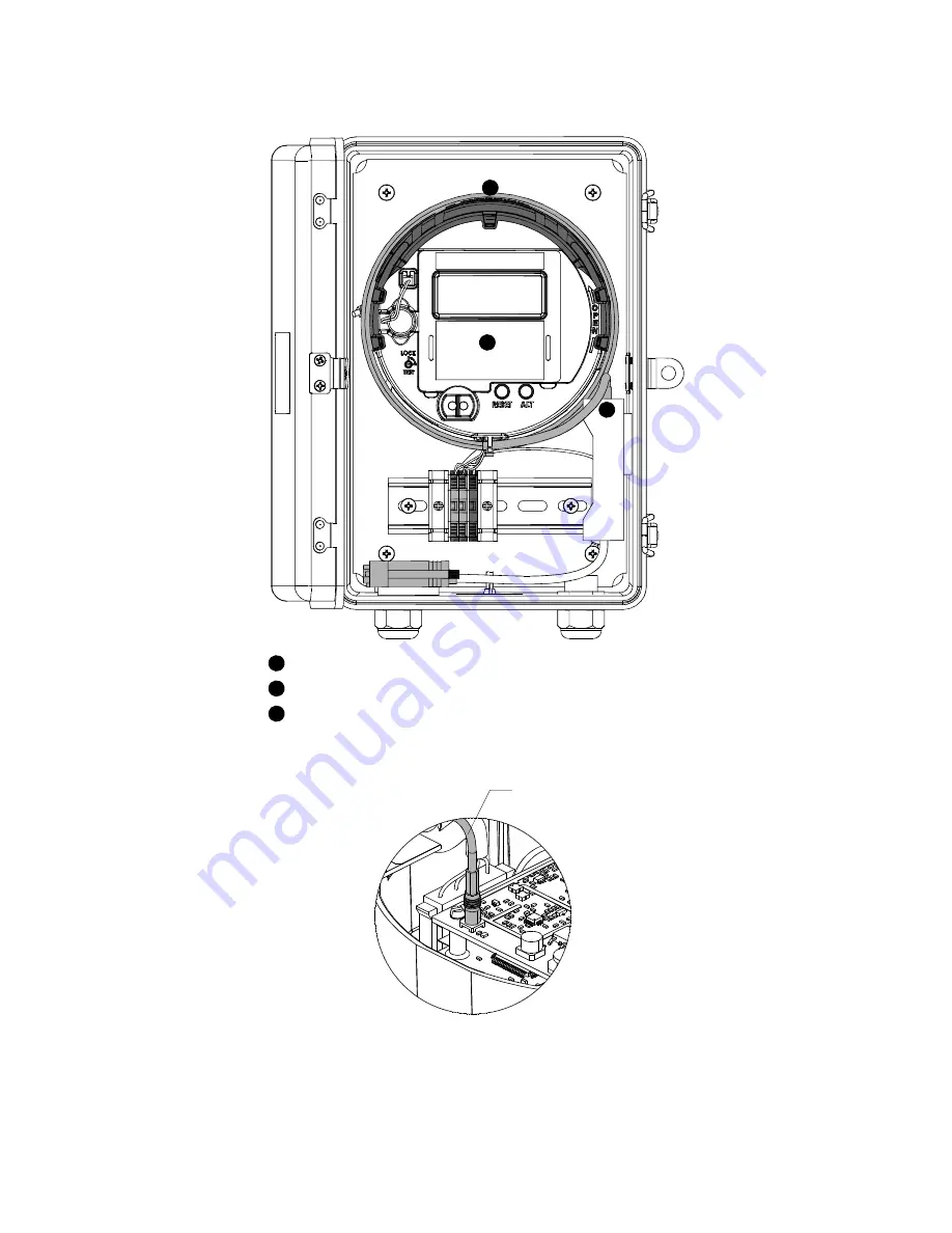
Figure 8. RS-232 communication option
Figure 9. Internal antenna cable
1
2
3
Communication cable
Kapton tape (if present)
Electronic assembly for collector
Antenna cable
Страница 1: ...A_Gatekeeper models EA_Gatekeeper with an AC power supply and battery backup EA_Gatekeeper with an AC power supply only EA_Gatekeeper with a solar power supply In addition this leaflet contains each model may use one of the following communication options Ethernet Cellular modem Telephone POTS PSTN modem RS 232 Unpacking the upgrade kit Visually inspect all parts for any damage during shipment con...
Страница 2: ...escription 5D25648G91 A3 ALPHA meter electronic assembly 1C11994G01 RJ 45 communication cable 7S1734H001 DC power cable not required or used in EA_Gatekeeper with AC power supply only 7S1755H001 Retention tape 7S1750H00X Model number label 7S1752H00X FCC ID label 7S1052H001 FCC ID label clear UV overlay 3A35340H01 Formed heat shrink tubing Style number Description 5D25648G91 A3 ALPHA meter electro...
Страница 3: ...l block that holds the cable 6 Rotate the electronic assembly counterclockwise and gently lift it from the meter base 7 Disconnect the AC voltage harness Figure 4 and the antenna isolation board RF cable Figure 5 from the electronic assembly 8 Remove the electronic assembly with the DC power cable and communication cable still attached to the electronic assembly How to install the RMA upgrade kit ...
Страница 4: ...tercat software After you install the electronic assembly for the gatekeeper firmware version 6 you must attach new labels to the enclosure 1 Attach the new model number label covering the existing model number label The model number label is located inside the enclosure door If an ESN is present transfer this number to the new label 2 Remove the clear overlay to FCC label and the existing FCC lab...
Страница 5: ... 5014B 5 Figure 1 Ethernet and telephone modem options 1 2 5 6 1 Circuit breakers 3 4 2 Fuse holder 3 Communication cable 4 Kapton tape if present 5 DC power cable and terminal block 6 Electronic assembly for collector ...
Страница 6: ...B October 2010 6 Figure 2 Cellular modem option 1 Circuit breakers 1 2 Fuse holder 2 3 3 Communication cable 4 4 Kapton tape if present 5 5 DC power cable and terminal block 6 6 Electronic assembly for collector ...
Страница 7: ...communication option Figure 4 Location of AC voltage harness 1 2 3 4 5 6 1 Circuit breakers 4 Kapton tape if present 2 Fuse holder 5 DC power cable and terminal block 3 Communication cable 6 Electronic assembly for collector AC voltage harness ...
Страница 8: ...rized utility procedures to install and service equipment Dangerous voltages are present Equipment damage personal injury and death can result if safety precautions are not followed Note The upgrade kit ships the electronic assembly with a DC power cord attached see Figure 6 The DC power cord is not used in or required by the EA_Gatekeeper with only AC power Remove the DC power cord and discard it...
Страница 9: ...October 2010 IL42 5014B 9 Figure 6 DC power cable DC power cable ...
Страница 10: ...otion about the top antenna mounting hole The antenna should then pull easily from its mounting hole and can be removed from the electronic assembly 7 Remove the existing electronic assembly with the communication cable still attached to the electronic assembly How to install the RMA upgrade kit 1 Unpack the RMA upgrade kit 2 Remove the tape securing wires to the side of the electronics module hou...
Страница 11: ...xisting model number label The model number label is located inside the enclosure door 2 Remove the clear overlay to FCC label and the existing FCC label Attach the new FCC label and apply the new clear overlay The FCC label is located on the outside of the enclosure Figure 7 Ethernet and telephone modem options 1 2 3 1 Communication cable 2 Kapton tape if present 3 Electronic assembly for collect...
Страница 12: ...IL42 5014B October 2010 12 Figure 8 RS 232 communication option Figure 9 Internal antenna cable 1 2 3 1 2 3 Communication cable Kapton tape if present Electronic assembly for collector Antenna cable ...
Страница 13: ...October 2010 IL42 5014B 13 Figure 10 AC voltage harness Figure 11 Internal antenna latches AC voltage harness Internal antenna TOP to Latches A B C D E A E ...
Страница 14: ...om the isolation board to the electronics module b Connect the communications cable to the surge suppressor or the crossover cable used for modem applications c Connect the AC voltage harness from the enclosure to the electronics module 4 Place the Kapton tape at the 12 o clock position to secure the electronic assembly to the meter base 5 Connect the communications or crossover for cellular modem...
Страница 15: ... 2010 IL42 5014B 15 Figure 12 Cellular modem model Figure 13 AC voltage harness 1 2 3 4 1 Circuit breakers 2 Communication cable 3 Kapton tape if present 4 Electronic assembly for collector AC voltage harness ...
Страница 16: ...cable by loosening the terminal block that holds the cable 5 Rotate the electronic assembly counterclockwise and gently lift it from the meter base 6 Disconnect the AC voltage harness Figure 4 and the antenna isolation board RF cable Figure 5 from the electronic assembly 7 Remove the electronic assembly with the DC power cable and communication cable still attached to the electronic assembly How t...
Страница 17: ...the carryover error Er1 000001 or the clock error Er3 030000 are displayed when the electronic assembly is powered on the errors should be reset using Metercat software Figure 14 Ethernet and telephone POTS PSTN options 1 Fuse holders 2 Communication cable 3 Kapton tape if present 4 Electronic assembly for collector 1 2 3 4 ...
Страница 18: ...IL42 5014B October 2010 18 Figure 15 RS 232 communication option 1 2 3 4 1 Fuse holders 2 Communication cable 3 Kapton tape if present 4 Electronic assembly for collector ...
Страница 19: ...er 2010 IL42 5014B 19 Figure 16 Cellular modem option Figure 17 RF isolation cable 1 Fuse holders Communication cable Kapton tape if present Electronic assembly for collector 2 3 4 1 2 3 4 RF isolation cable ...
Страница 20: ...usive or covering all contingencies If further information is required Elster should be consulted No warranties either expressed or implied including warranties of fitness for a particular purpose or merchantability or warranties arising from the course of dealing or usage of trade are made regarding the information recommendations descriptions warnings and cautions contained herein In no event wi...