background image

User Manual: X-Series Rev A AiO Touchcomputer 

SW602213 Rev A, Page 24 of 51


8. 

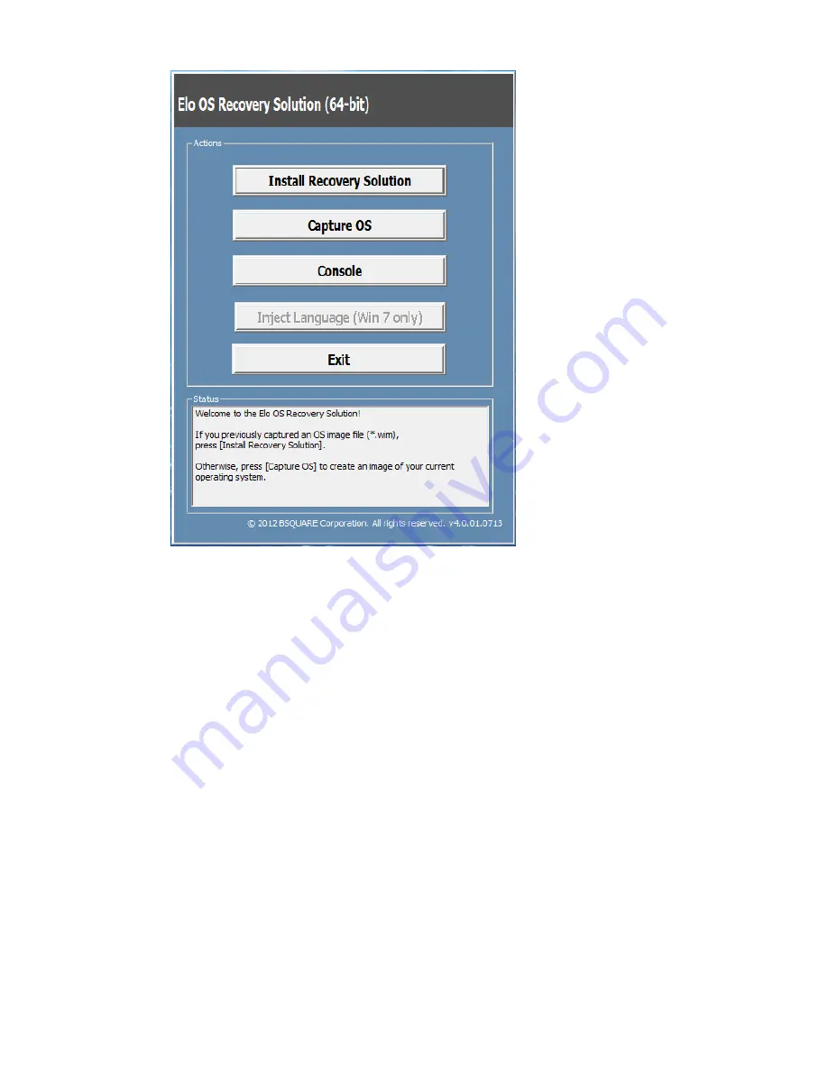
When the following UI is presented, click “Install Recovery Solution” button. 


9. 

Follow the on-screen instructions to complete the installation process and then exit 
the program. 


Note: All data is deleted during the recovery process. The user must back up files when 

necessary. Elo Touch Solutions does not accept liability for lost data or software. 

Note: The end user must adhere to Microsoft's Licensing Agreement


Содержание 17" X-Series

Страница 1: ...r Manual X Series Rev A AiO Touchcomputer SW602213 Rev A Page 1 of 51 USER MANUAL Elo Touch Solutions 15 X Series Rev A All in One Touchcomputer 17 X Series Rev A All in One Touchcomputer SW602213 Rev...

Страница 2: ...without notice Elo Touch Solutions Inc and its Affiliates collectively Elo makes no representations or warranties with respect to the contents herein and specifically disclaims any implied warranties...

Страница 3: ...6 L E D Functionality POWER LED 17 L E D Functionality Wireless LAN LED 17 L E D Functionality Ethernet LAN LED 18 Using the Input output Panel 18 Setting Up the Operating System 19 Creating the Recov...

Страница 4: ...energy your computer is set to dim the display after 5 minutes of inactivity and enter the low power Sleep mode which shuts down the system after 30 minutes of inactivity We recommend that you leave t...

Страница 5: ...your responsibility to ensure that your X Series have adequate protection in the form of firewalls antivirus software and anti spyware software and keep them up to date Keep electrical appliances such...

Страница 6: ...orporates a 24 bit color 1024x768 15 1280X1024 17 LCD panel to provide superior display performance for displaying graphics and images and running applications The X2 models are fan less well suited f...

Страница 7: ...X Series Rev A AiO Touchcomputer SW602213 Rev A Page 7 of 51 X Series Layout Figure 1 X Series front view left clerk right side view middle and back view right Figure 2 X Series back view up and rear...

Страница 8: ...technology is defined as below touch type for composition of the system AccuTouch micro bezel resistive Intellitouch Plus zero bezel multi touch surface acoustic wave Intellitouch single touch surface...

Страница 9: ...power connector to power up the X Series system 12 24V Power USB Port X3 X5 X7 only The 24V Power USB Port spec is design for X3 X5 X7 configuration only The maximum power rating of the 24V Power USB...

Страница 10: ...en user fact to the X series system 21 Microphone built in The microphone port is built in design for user can be connected to the X Series system 22 Cable Exit Hole The cable exit hole is design for...

Страница 11: ...em 2 Serial Port RS 232 The serial port is a standard native RS 232 interface for connection 3 Ethernet LAN Port The Ethernet LAN Port has gigabyte speed capability for network of the X Series 4 12V P...

Страница 12: ...d in good condition X Series system unit Quick Install Guide AC DC Power adapter Power cable for North America Europe and U K Cable Cover Locking Screw 3 Remove the protection bag cover desiccant pack...

Страница 13: ...The X Series all in one touchcomputer has two title positions for different scenario to use It can through the two screws of the stand bottom to adjust the low and high position The title adjust is sh...

Страница 14: ...Calibrating The touchscreen is pre calibrated for accurate touch response If for any reason the touchscreen needs to be recalibrated double click the Elo Alignment shortcut on the system desktop for W...

Страница 15: ...SW602213 Rev A Page 15 of 51 Note X Series IntelliTouch Pro projective capacitive models are fully HID compliant so they do not need to be calibrated and configured Therefore EloConfig tool does not...

Страница 16: ...matically saved User settings remain unchanged after powering off on or in the case of a power failure Front OSD Control Buttons The control buttons provide the following functions from left to right...

Страница 17: ...LED Color to Observer State Off No input power Off mode Red Input power present Off mode or hibernation Orange Input power present Standby Green Input power present Power On L E D Functionality Wirel...

Страница 18: ...No Link No Color Linked Solid Green Color Data Activity Blinking Green Color Using the Input output Panel To access the input output I O ports remove the cable cover at the bottom of the unit A secur...

Страница 19: ...System for the touchcomputer turn on the touchcomputer by pressing the power button and then follow the on screen instructions Injecting a new language Windows only allows the use of only one language...

Страница 20: ...anual X Series Rev A AiO Touchcomputer SW602213 Rev A Page 20 of 51 4 Select either Restore OS 32bit or Restore OS 64bit depending on your OS environment 5 The following User Interface UI will be pres...

Страница 21: ...reference language 8 Click Inject Selected Language 9 While the injecting process is performing DO NOT use your keyboard or mouse during this time It may cause an error in the language injection proce...

Страница 22: ...immediately In the event the HDD SSD recovery partition is accidentally deleted or becomes inaccessible you will need to use the recovery flash drive to recover your system The following procedures de...

Страница 23: ...depending on your system configurations and flash drive performance 6 Once the message says Creation Restore Media success please remove the flash drive and click Exit to exit the program 7 In case t...

Страница 24: ...n button 9 Follow the on screen instructions to complete the installation process and then exit the program Note All data is deleted during the recovery process The user must back up files when necess...

Страница 25: ...ocedures below PLEASE NOTE THAT ALL CUSTOMER SETTINGS AND DATA WILL BE LOST DURING THIS PROCESS Please be sure to completely backup all of your data settings and customer installed software before pro...

Страница 26: ...mputer SW602213 Rev A Page 26 of 51 5 The following User Interface UI will be presented 6 Select Restore OS System will test your hardware automatically Once the process completes click Start button t...

Страница 27: ...ess 8 Once completed click the Close button The system will return to the main menu of the Elo Recovery Solution Then click the Exit button to restart your system NOTE All data is deleted during the r...

Страница 28: ...vailable for purchase from Elo Touch Solutions Shown in parenthesis is the Elo orderable part number Biometric Fingerprint Reader KIT E001001 Fingerprint reader with USB interface for all X Series con...

Страница 29: ...s can be found in the following directory or on www elotouch com C EloTouchSolutions Peripherals The fingerprint reader is powered by the USB bus The reader optically scans the fingerprint when the us...

Страница 30: ...0 of 51 FPR allocation on X Series Testing the FPR 1 Double click the Fingerprint Reader Test icon to start the test application 2 Place your finger on the fingerprint reader sensor and verify that th...

Страница 31: ...language capability The credit card is read by sliding the credit card forward or backward through the MSR stripe side toward the display The MSR is powered from the USB port no external power is nee...

Страница 32: ...g in USB MSR Keyboard KB Emulation Mode 1 Open the Notepad application click Start Accessories Notepad 2 Slide the card through the MSR and verify that the data is displayed in the application window...

Страница 33: ...display to the X Series touchcomputer to any of the three mounting locations located on the display head top left and right of the touchcomputer Software application and drivers can be found in the fo...

Страница 34: ...9 2 W x 5 5 H mm Character Number 20 x 2 Character Type 95 Alphanumeric 32 International Characters Dot Size 0 86 x 1 2 mm Brightness 500 1000 cd m2 Viewing Angle Max 90 Panel Dimension 220 W x 50 D...

Страница 35: ...compliant ISO 18092 compliant Encryption Encrypted card data AES or Triple DES DUKPT key management with more than 2M keys model selectable Authentication with RSA 2048 bit key Payment applications Am...

Страница 36: ...ers can be found in the package or on www elotouch com Note Requires POLE MOUNT KIT for hold up the second display kit Part number E038989 Feature Description Display type 7 diagonal Active matrix TFT...

Страница 37: ...eral part for all X Series configurations The Expansion Module KIT specifications are shown in below table Feature Spec Description Serial Port 1 Native RS 232 Serial Port 2 Native RS 232 Ethernet Por...

Страница 38: ...E038989 You can optionally add a POLE MOUNT STAND KIT to combine with stand module of the X Series touchcomputer for all X Series configurations The POLE MOUNT STAND KIT is ability to support 7 15 cus...

Страница 39: ...Touchcomputer SW602213 Rev A Page 39 of 51 WALL MOUNT KIT E143088 You can optionally add a WALL MOUNT KIT to X Series touchcomputer at wall through two mental frames for all X Series configurations WA...

Страница 40: ...he BARCODE SCANNER peripheral shall have a USB connection to interface with the X Series touchcomputer Feature Spec Description Light Source 660nm visible LED Optical sensor 2500 pixels Toshiba CCD se...

Страница 41: ...lank 1 If the Power Status LED is blinking the X Series may be in SLEEP mode Press the power button to see if the image reappears 2 Internal cable loss or electrical part damage No Operation System 1...

Страница 42: ...ith an AC DC power adapter Do not use a damaged AC DC power adapter Use only the AC DC power adapter supplied by Elo Touch Solutions for the X Series Use of an unauthorized AC DC power adapter may inv...

Страница 43: ...ies Disconnect the power cable before cleaning To clean the X Series except touchscreen use soft cotton or microfiber cloth lightly dampened with a mild detergent It is important that your unit remain...

Страница 44: ...he end of its useful life according to local laws and regulations Elo has put in place recycling arrangements in certain parts of the world For information on how you can access these arrangements ple...

Страница 45: ...2 this device must accept any interference received including interference that may cause undesired operation Note This equipment has been tested and found to comply with the limits for a Class B dig...

Страница 46: ...in the European Union Use only the provided power cords and interconnecting cabling provided with the equipment Substitution of provided cords and cabling may compromise electrical safety or CE Mark...

Страница 47: ...er are on different branch circuits V Disconnect and remove any I O cables that the digital device does not use Unterminated I O cables are a potential source of high RF emission levels VI Plug the di...

Страница 48: ...Pb Mercury Hg Cadmium Cd Hexavalent Chromium Cr6 Polybrominated Biphenyls PBB Polybrominated Diphenyl Ethers PBDE Plastic Parts O O O O O O Metal Parts X O O O O O Wire and Cable Assembly X O O O O O...

Страница 49: ...rating conditions listed below so that the use of this electronic information product will not result in any severe environmental pollution any bodily injury or damage to any assets Operating Temperat...

Страница 50: ...User Manual X Series Rev A AiO Touchcomputer SW602213 Rev A Page 50 of 51 Chapter 8 Warranty Information For warranty information go to http www elotouch com Support warranty asp...

Страница 51: ...ely Elo makes no representations or warranties with respect to the contents herein and specifically disclaims any implied warranties of merchantability or fitness for a particular purpose Elo reserves...

Отзывы: