background image

15

MECHANICAL ADJUSTMENT
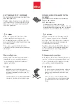
TOP TENSION

The top tension should be between 75 to 90 gf when pulling the thread (polyester sewing thread #50 (white)) up 

in the direction of arrow (Make sure the the foot is lowered) with the tension dial at “4”.

If the tension is out of the range, adjust as follows:

1. Remove the front cover (Refer to page 6). 

2. Set the tension dial at “4”.

3. After threading the upper thread, lower the presser foot.

    • If the top tension is too tight, turn the lead screw in the direction A. 

    • If the top tension is too loose, turn the lead screw in the direction B. 

4. Check the top tension and attach the front cover.

Polyester sewing thread #50 (white)

Pull the thread at the speed of 110 mm/sec in the direction of arrow.

Содержание Elnita ec 30

Страница 1: ...SERVICE MANUAL MODEL ec 30 First Edition 25 June 2020...

Страница 2: ...OTARY HOOK 12 FEED DOG HEIGHT 13 BACKLASH BETWEEN HOOK GEAR AND LOWER SHAFT GEAR 14 TOP TENSION 15 STRETCH STITCH FEED BALANCE 16 REPLACEMENT AND ADJUSTMENT OF THE NEEDLE THREADER PLATE 17 SELF DIAGNO...

Страница 3: ...d sewing needle and the thread Use a HAx1 11 blue tip needle See mechanical adjustment Adjustment of Needle bar height See mechanical adjustment Adjustment of Hook timing See mechanical adjustment Cle...

Страница 4: ...ead 1 Bobbin holder is incorrectly threaded 2 Too much thread is wound on the bobbin 3 Lint is stuck inside the bobbin holder 4 Thread quality is too low 5 Thread is jamming around the bobbin holder S...

Страница 5: ...ot enough oil 5 Upper shaft gear is loose Eliminate the backlash Eliminate the looseness See part removal and replacement Driving motor DC motor Oil all moving parts Eliminate the looseness P 14 P 14...

Страница 6: ...4 CHANGING EXTERNAL PARTS FACE COVER To remove 1 Remove the setscrew q 2 Remove the face cover w To attach 3 Follow the above procedure in reverse w q...

Страница 7: ...e the setscrew q 2 Remove the setscrew w 3 Move the bed cover e to the left to unlock the cover 4 Slide the bed cover to the up to remove the cover To attach 5 Follow the above procedures in reverse C...

Страница 8: ...Loosen the setscrew r 6 Remove the setscrew t 7 Disengage the front cover and rear cover hooks 8 Remove the front cover y 9 Disconnect all the connectors from the circuit board A NOTE Do not disconnec...

Страница 9: ...face cover bed cover and front cover Refer to pages 4 to 6 2 Remove the setscrew q 3 Remove the setscrews w 4 pcs 4 Remove the rear cover e 5 Disengage the rear cover e and thread tension hooks r To a...

Страница 10: ...ick block under the presser foot and lower the presser foot lifter 3 Loosen the hexagonal socket screw Raise the presser foot lifter and tighten the setscrew firmly Attach the needle and face plate NO...

Страница 11: ...emove the face cover Refer to page 4 3 Set the stitch width to 5 0 4 Make the following adjustments if the clearance between the needle drop position and the adge of the needle are even for both sides...

Страница 12: ...socket screws on the lower shaft gear 5 Turn the handwheel toward you to raise the needle bar 1 7 mm from its right lowest position 6 While holding the handwheel to prevent the needle bar from moving...

Страница 13: ...setscrew on the needle plate the needle plate and the bobbin holder 4 Turn the handwheel toward you until the hook point meets the right side of the needle 5 Loosen the hexagonal socket screw and mov...

Страница 14: ...presser bar base plate in the direction of C when the clearance it too small Adjust the clearance betweeen the needle and hook betweeen 0 10 to 0 05 mm Tighten the setscrews The edge of presser bar ba...

Страница 15: ...e plate should be 0 80 to 0 95 mm If it is not in the range adjust as follows To adjust 3 Loosen the screw A 4 Turn the handwheel to bring the feed dog to its highest position 5 If the feed dog height...

Страница 16: ...A If the rotary play is too large turn the lower shaft bussing in the direction of B If the rotary play is too small turn the lower shaft bussing in the direction of C 4 Tighten the setscrew A 5 Atta...

Страница 17: ...of the range adjust as follows 1 Remove the front cover Refer to page 6 2 Set the tension dial at 4 3 After threading the upper thread lower the presser foot If the top tension is too tight turn the l...

Страница 18: ...f 10 pieces of the triple stitch pattern is shorter than 25 mm Turn the hexagonal socket screw in the direction of B if the total length of 10 pieces of the triple stitch pattern is longer than 27 mm...

Страница 19: ...knob and pull the threader plate supporter down to remove it see FIG 1 2 To install the needle threader plate line the groove up with the pin and push it up to snap fit TO ADJUST THE THREADER PLATE PO...

Страница 20: ...n Turn on the switch If any of the following problems occur take the recommended actions in the order they are shown 1 The machine does not respond when the power switch is turned on Check each connec...

Страница 21: ...utton y is pressed LED displays 7 when button u is pressed When q to u are pressed LED displays b as shown LED displays 3 When the bobbin winder spindle is moved to the right buzzer sounds and LED dis...

Страница 22: ...sound Stitch width or length symbol does not appear REMEDY Replace the circuit board A 06 ZIGZAG MOTOR STEP MOTOR AND FEED MOTOR LED displays 5 Turn the handwheel LED displays the top bar symbol when...

Страница 23: ...is defective condition press the reverse stitch button to proceed the next step 08 SLIDE VOLUME Press the needle up down button If the result is correct condition press the MODE key to proceed the nex...

Страница 24: ...d The defective part number Refer to pages 19 to 21 Steps and items section Press the reverse stitch button to return to 01 Turn the power switch off when the self diagnostic test is finished TO DISPL...

Страница 25: ...G THE ELECTRONIC COMPONENTS Not applicable for this machine Printed circuit board L White Printed circuit board P Black Switching ragulator White ErP switch Red Feed motor White DC motor White Bobbin...

Страница 26: ...Remove the setscrews 4 pcs and the printed circuit board A TO ATTACH 4 Follow the above procedures in reverse NOTE Do not disconnect the connectors by pulling on cord To disconnect grasp the connecto...

Страница 27: ...emove the setscrew and LED cover 4 Remove the snap rings CS 2 pcs 5 Remove the printed circuit board L TO ATTACH 6 Follow the above procedures in reverse NOTE Do not disconnect the connectors by pulli...

Страница 28: ...and the motor belt Tighten them with setscrews 2 pcs lightly 4 Move the motor up or down to adjust the motor belt tension The belt should deflect 7 to 9 mm when applying 300 grams force of load to the...

Страница 29: ...hing regulator with cords TO ATTACH 3 Follow the above procedures in reverse Be sure to connect the connectors switching regulator connector white and ErP switch connector Red to the circuit board A R...

Отзывы: