background image


44 of 124  |  

Electrical Tests


Ex

ami

n

er

 U

se

G

u

ide


Test Steps and Expected Results 

1.


Examiner brings the link to the U0 state. 

2.


Examiner issues one or more standard descriptor requests. 

3.


Examiner places the device into each device state (configured, addressed, and default) in 

three separate tests before commanding the device to enter U3 in each test.  Current is 

measured once the link is in U3, as described below. 

4.


Examiner issues an LGO_U3 link command. 

The device must reply with an LAU link command. 

5.


Examiner issues an LPMA link command to place the link into U3. 

In all three tests, the device must draw less than [2.5ma] 150ma. 

Specification Reference 

Section 11.4.3 

5.5


VBus Acceptance Range Tests 

Test Summary 

This test verifies that the PUT reaches and maintains U0 across a range of decrementing VBus 

levels.  Examiner will vary the VBus level from 5.30V to 3.60V in 100mV decrements for each 

test.   Examiner will report current, power and VBus for each test. 


Test results for VBus levels between 3.60V and 4.40V are below required 

levels (per specification) and are advisory only. 

Test Steps and Expected Results 

1.


Examiner brings the link to the U0 state using the first VBus level (5.30V). 

2.


Examiner issues one or more standard descriptor requests. 

3.


Examiner places the device into each device state (configured, addressed, and default) in 

three separate tests, each including all VBus range increments. 

4.


Examiner measures current, power, and VBus during U0. 

Содержание USB Explorer 280

Страница 1: ...USB Explorer 280 Examiner Compliance Test Suite User Manual Version 1 03 January 18 2013...

Страница 2: ...responsibility for errors or omissions contained in this book This publication and features described herein are subject to change without notice Copyright C Ellisys 2011 All rights reserved All produ...

Страница 3: ...Layer Test Specification October 26 2011 1 0 USB 3 0 Specification November 12 2008 1 0 USB 3 0 Errata June 9 2010 N A Ellisys Contact Details Ellisys Phone 41 22 777 77 89 Chemin du Grand Puits 38 Fa...

Страница 4: ...hipped at Ellisys expense Repaired or replacement product will continue to be covered by this limited warranty for the remainder of the original warranty or 90 days whichever is longer Limitations THE...

Страница 5: ...s Storage Testing 26 3 2 Setup for Chapter 10 Hub Testing 29 3 3 Using USB30CV 31 3 4 USB Explorer 280 Front Panel Overview 33 3 5 Explorer 280 Back Panel Overview 35 4 User Interface Reference 38 4 1...

Страница 6: ...Port Only 71 7 21 PM_LC_TIMER Timeout Test Downstream Port Only 72 7 22 PM_ENTRY_TIMER Timeout Test Upstream Port Only 73 7 23 Accepted Power Management Transaction for U1 Test Upstream Port Only 73...

Страница 7: ...est 106 8 20 Optional Commands Test 107 9 Device Framework Tests 109 9 1 Device Descriptor Test 109 9 2 Standard Configuration Descriptor Test 110 9 3 Reserved 111 9 4 Standard Interface Descriptors T...

Страница 8: ...8 of 124 Examiner User Guide 10 Hub Tests 124...

Страница 9: ...ice or hub upstream port 26 Figure 3 3 Examiner Setup for Testing Host 27 Figure 3 4 Examiner Setup for Testing Hub Downstream Facing Port 28 Figure 3 5 Test Setup for Hub Chapter 10 Tests 29 Figure 3...

Страница 10: ...o respond to a situation that may arise A tip symbol tells you information that will help you carry out a procedure Where to Find More Help Go to the Ellisys website and the following pages for the la...

Страница 11: ...r a Downstream Port Under Test The Link Verification System Examiner will act as the opposite port LVS See Link Verification System Port Under Test The port connected to the Link Verification System u...

Страница 12: ...t is used to verify proper operation of a USB 3 0 host hub or device based on requirements as set forth in the USB 3 0 specification and other relevant documents as provided by the USB Implementers Fo...

Страница 13: ...wnstream port For Chapter 10 testing two enabled EX280s are used to emulate US and DS ports of the hub under test HUT See Section 3 Hardware Setup and Configurations for details Optionally an Explorer...

Страница 14: ...lable at the completion of testing see figure 1 3 below which includes links to automatically saved traces for each test as captured by the analyzer Figure 1 3 Sample HTML Compliance Report The EX280...

Страница 15: ...tests for Voltage Power and Current in U0 U1 U2 and U3 states Mass Storage Class Some tests are conducted in three different device states Default Addressed and Configured Expected results for each st...

Страница 16: ...6 colors or better USB 2 0 EHCI Host Controller Examiner requires several software components Ellisys recommends that you visit the following web pages as needed to update your versions of Microsoft N...

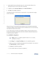
Страница 17: ...Examiner Setup Wizard screen appears If the Examiner Setup Wizard does not appear automatically navigate to the location of the EllisysUSB30Examiner installer file through the Windows directory and la...

Страница 18: ...Installing the Application Examiner User Guide The License Agreement screen appears 3 Read the License Agreement carefully and then select I Agree 4 Click on Next The Select Installation Folder scree...

Страница 19: ...at you use the default folder however if you wish to change this folder click on Browse and navigate to the folder required 6 Select whether anyone or only the user currently logged on can access the...

Страница 20: ...ication Examiner User Guide An Installation Progress screen appears When the software has been installed the Installation Complete screen appears 8 Click on Close The Ellisys USB Explorer 280 Examiner...

Страница 21: ...strongly recommends that you connect it to a high speed USB 2 0 port to obtain optimal performance If you experience problems with Examiner please ensure the Explorer 280 executing Examiner is connec...

Страница 22: ...talling the Application Examiner User Guide The Hardware Update Wizard opens 7 Select No not this time 8 Click on Next The Found New Hardware Wizard appears 9 Select Install the software automatically...

Страница 23: ...SB Explorer 280 10 Click on Next The Please wait while the wizard installs the software window appears Windows installs the driver 11 When the installation is complete the wizard has finished installi...

Страница 24: ...24 of 124 Installing the Application Examiner User Guide The installation is complete...

Страница 25: ...s during each test that is executed This section describes test setups for the following cases Section 3 1 Device and Host Link Layer Tests Chapters 6 7 These are required for USB IF certification for...

Страница 26: ...r s tests Optionally connect another USB 2 0 cable to the rear control port of an Explorer 280 Analyzer in order to capture the traffic occurring between the PUT and Examiner Examiner will control the...

Страница 27: ...control port of an Explorer 280 Analyzer in order to capture the traffic occurring between the port under test PUT and Examiner Examiner will control the analyzer as well If not connecting the analyze...

Страница 28: ...DFP the upstream facing port of the hub must be connected to a host system that has USB30CV installed Connect as shown in the figure below Ensure USB30CV is loaded on the host system The DC power supp...

Страница 29: ...t USB 2 0 cables to the rear control ports of both Explorer 280 Analyzers in order to capture the traffic occurring between the US port under test PUT and Examiner US and between the DS port under tes...

Страница 30: ...30 of 124 Hardware Setup and Configurations Examiner User Guide Figure 3 6 Test Setup for Hub Chapter 10 Tests Without Analyzers...

Страница 31: ...trol some of the Link Layer tests in conjunction with Examiner as shown in the figure below and will also provide VBUS to the hub which is required for all Link Layer tests on a hub downstream port If...

Страница 32: ...nstructing the user to initiate an action on CV such as issuing a Get Descriptor request as shown above For any further Examiner tests that require USB30CV initiation of host side actions such as send...

Страница 33: ...re excluded from the Examiner s test list USB30CV is not needed for this test selection To Run only USB30CV tests 1 Select USB CV Tests Only from the Tests Selection drop down menu on Examiner All tes...

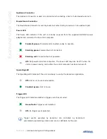
Страница 34: ...perate Flashing green Powered but not connected Flashing red Connected but not powered Off Not powered and not connected The Power LED may also be off if when the unit is in power saving mode after th...

Страница 35: ...rSpeed signaling detected Constant green 5Gb s SuperSpeed signaling detected receiver synchronized Flashing red Link is unstable frequent loss of synchronization Receive LED The Receive LED indicates...

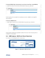
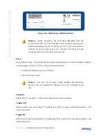
Страница 36: ...he nearby LED illuminates constant green if a correct voltage is applied and illuminates constant red if the voltage is applied reversed Accepted Voltage Range 12V to 24V DC Minimum Power 18W Caution...

Страница 37: ...Hardware Setup and Configurations 37 of 124 SuperSpeed USB Explorer 280 Auxiliary Equipment Reserved for future extensions Inter equipment Reserved for future extensions...

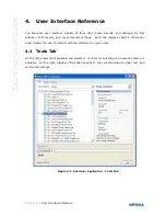
Страница 38: ...environmental settings Each tab displays specific information and or allows the user to interact with the software for a given task 4 1 Tests Tab On the left shows tests available and selected Control...

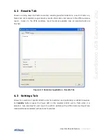
Страница 39: ...t Access to the HTML summary report becomes available once all selected tests are finished Figure 4 2 Examiner Application Results Tab 4 3 Settings Tab Allows for selection of specific EX280 units for...

Страница 40: ...cation Settings Tab In some cases the user may prefer to capture activity between Examiner and the PUT using an EX280A analyzer without automated control from Examiner i e under the control of the EX2...

Страница 41: ...has been assigned a unique non zero address and has been configured by Examiner to use the function provided by the device 5 1 U0 Power Consumption Test Summary This test verifies that the PUT s powe...

Страница 42: ...nd default states using a Link Management Packet LMP Examiner will report current power and VBus for each test Test Steps and Expected Results 1 Examiner brings the link to the U0 state 2 Examiner iss...

Страница 43: ...ressed and default in three separate tests before commanding the device to enter U2 in each test Current is measured once the link is in U2 as described below 4 Examiner issues a Set Link Functionalit...

Страница 44: ...Specification Reference Section 11 4 3 5 5 VBus Acceptance Range Tests Test Summary This test verifies that the PUT reaches and maintains U0 across a range of decrementing VBus levels Examiner will v...

Страница 45: ...ch U0 and maintain U0 until Examiner disables the link 5 Examiner disables the link to force link recovery then repeats the process for the next VBus increment to be tested This process is repeated un...

Страница 46: ...proper understanding of test sequences that are conducted in Chapters 6 and 7 tests In some tests however control transfers are used and in these tests the user may find it more intuitive to leave Gr...

Страница 47: ...Repetition of four skip ordered sets followed by 1 415 symbols word misaligned Test Steps and Expected Results 1 Examiner brings the link to U0 as described in TD7 1 Link Bring Up Test then uses the f...

Страница 48: ...quency Test Test Summary This test verifies that the PUT s LFPS detector supports the entire LFPS frequency range permitted Here are the periods to be tested tPeriod 10 MHz minimum 100ns tPeriod 50 MH...

Страница 49: ...tBurst 1 4 us and tRepeat 14 us Test Steps and Expected Results 1 Examiner and the PUT go through the initial steps of the LTSSM SS Disabled Rx Detect to reach Polling LFPS 2 Examiner will generate a...

Страница 50: ...to as the Link Verification System LVS This is intended to maintain consistency with USB IF compliance documents and procedures These terms may be considered synonymous within this manual Certain link...

Страница 51: ...ner sends at least 2 consecutive Polling LFPS The PUT must progress past Polling LFPS before tPollingLFPSTimeout expires 360ms 50 3 Examiner transmits TSEQ ordered sets The PUT must transmit TSEQs The...

Страница 52: ...s is permitted The PUT must NOT continue to send TS2s after tPollingConfigurationTimeout expires 12ms 50 6 Examiner transmits IDLE symbols The PUT must transmit 16 IDLEs after its TS2s The PUT must NO...

Страница 53: ...cutes the steps described in TD7 1 Link Bring Up Test to bring the link to U0 but transmits all LCRD_X link commands with an error in the first LCSTART symbol The test passes if the exchanges are met...

Страница 54: ...second and third conditions listed above Specification Reference Section 7 3 4 2 7 4 Invalid Link Command Test Test Summary This test verifies that the PUT will ignore an invalid link command first an...

Страница 55: ...s all Header Packets with an error in the first HPSTART symbol 2 Repeat the above steps with an error in the second third and fourth HPSTART symbols The test passes if the exchanges are met no timeout...

Страница 56: ...r executes the steps described in TD7 1 Link Bring Up Test to bring the link to U0 At this stage the Downstream Port either Examiner or the host port under test is expected to issue a Get Device Descr...

Страница 57: ...met no timeout is detected all packets are successfully received by the PUT all credits are restored and the link stays in U0 for at least 50ms The test fails if the data exchange fails at the protoco...

Страница 58: ...K Character is inserted into the LMP packet This is done in order to better simulate an in flight transmission error rather than a chip error on the PUT Test Steps and Expected Results 1 Examiner exe...

Страница 59: ...LUP when Examiner is configured as Upstream Port LDN when Examiner is configured as a Downstream Port 3 Repeat the above steps for each of the invalid conditions listed above The test passes if the ex...

Страница 60: ...as a Downstream Port a It waits for the PUT s Port Capability LMP b It transmits its Port Capability LMP c It responds to the PUT with an LBAD d It waits for the PUT to transmit an LRTY e It waits for...

Страница 61: ...ansmits all LGOOD_N responses at PENDING_HP_TIMER tLinkTurnAround The PENDING_HP_TIMER deadline value is 3us The value of tLinkTurnAround is 500ns and is defined in the USB 3 0 Link Layer Test Specifi...

Страница 62: ...go to recovery when the PENDING_HP_TIMER expires Test Steps and Expected Results 1 Examiner performs steps 1 to 3 of TD7 1 Link Bring Up Test to bring the link to U0 2 Examiner and the PUT will exchan...

Страница 63: ...4 1 10 1 Table 7 7 7 12 CREDIT_HP_TIMER Timeout Test Test Summary This test verifies that the PUT will go to recovery when the CREDIT_HP_TIMER expires Test Steps and Expected Results 1 Do steps 1 to 4...

Страница 64: ...urnAround after reception of the second LMP packet with the repeated Header Sequence Number of 0 The value of tLinkTurnAround is 500ns and is defined in the USB 3 0 Link Layer Test Specification Secti...

Страница 65: ...and Expected Results 1 Examiner performs steps 1 to 4 of TD7 1 Link Bring Up Test with the exception that Examiner will send an LCRD_A for the first LMP packet as expected but will send again an LCRD...

Страница 66: ...es not go to Recovery within tU0RecoveryTimeout expiration 1 5080ms Note that the time calculation above is not from the start of U0 to the start of the recovery sequence it is from the last link comm...

Страница 67: ...on calculated test time 20 6us The test fails if the PUT transitions to SS Disabled before tPortConfiguration deadline 20us or sends any other packets or LFPS signals at this point 2 Examiner performs...

Страница 68: ...the PUT transitions to SS Inactive before tPortConfiguration deadline 20us or sends any other packets or LFPS signals at this point 2 Examiner performs steps 1 to 3 of TD7 1 Link Bring Up Test to bri...

Страница 69: ...the link to U0 2 Examiner application prompts the test operator to enable and configure the U1 and U2 inactivity timers through USB30CV CV will set the U1 Timeout field to 7Fh and the U2 Timeout field...

Страница 70: ...U2 Test Downstream Port Only Test Summary This test verifies that the PUT initiates U2 state Test Steps and Expected Results 1 Examiner performs steps 1 to 4 of TD7 1 Link Bring Up Test to bring the l...

Страница 71: ...USB 3 0 Link Layer Test Specification Section 4 Please refer to that document for details The test passes if all transactions are correct no extra packets or LFPS signals are received and the PUT ent...

Страница 72: ...uests from the PUT with LXU 5 After Examiner completes this test case clear the U1 U2 registers through the CV prompt Specification Reference Section 7 2 4 1 1 2 7 21 PM_LC_TIMER Timeout Test Downstre...

Страница 73: ...tream Port Only 2 Examiner does not transmit LPMA when it receives LAU The value of PM_ENTRY_TIMER deadline is 6us but is given a calculated test time expiration of 9 545us This calculated test time i...

Страница 74: ...ons from section 6 9 2 Between 300ns 900ns elapses between the start of Examiner U1 Exit LFPS and the start of the PUT U1 Exit LFPS The PUT U1 Exit LFPS duration is within 600ns 900ns Specification Re...

Страница 75: ...NoLFPSResponseTimeout U1 U2 after the start of its U2 Exit LFPS The value tNoLFPSResponseTimeout for U1 U2 is 2ms but is given a calculated test time of 2 0105ms This calculated test time is defined i...

Страница 76: ...U3 after the start of its U3 Exit LFPS The value tNoLFPSResponseTimeout for U3 is 10ms but is given a calculated test time of 10 0505ms This calculated test time is defined in the USB 3 0 Link Layer...

Страница 77: ...5 10 4 2 1 7 5 10 5 1 1 7 5 10 5 2 1 7 27 Hot Reset Detection in Polling Test Upstream Port Only Test Summary This test verifies that the PUT detects the Hot Reset in Polling Test Steps and Expected R...

Страница 78: ...the Hot Reset in U0 and does not start the Port Configuration Sequences Test Steps and Expected Results 1 Examiner performs steps 1 to 5 of TD7 1 Link Bring Up Test to bring the link to U0 2 Examiner...

Страница 79: ...ed Results 1 Do steps 1 to 5 of TD7 1 Link Bring Up Test to bring the link to U0 2 Examiner prompts the test operator to initiate a Hot Reset on the PUT through USB30CV 3 Examiner waits for TS1s from...

Страница 80: ...l enter Recovery if it fails to receive a header packet three consecutive times Test Steps and Expected Results 1 Examiner performs steps 1 to 3 of the Link Initialization Sequence 2 Examiner and the...

Страница 81: ...esponds to the first two invalid packets with an LBAD The PUT initiates a Recovery within tLinkTurnAround after the third invalid packet and does not send an LBAD at this point The Recovery is not ini...

Страница 82: ...nt for details The test fails if the PUT does not transmit a Warm Reset LFPS within tHotResetTimeoutToWarmReset 12ms to 18 5ms 5 Examiner responds to the Warm Reset LFPS by entering Rx Detect 6 Examin...

Страница 83: ...OMs in the 4th Compliance Pattern The test fails if Examiner cannot verify a Compliance Pattern coming from the PUT 6 Examiner transmits a Warm Reset LFPS and enters Rx Detect 7 Examiner and PUT perfo...

Страница 84: ...to receive a Warm Reset LFPS from the PUT The test fails if Examiner does not receive a Warm Reset LFPS before the test operator hits OK 7 Examiner closes the prompt automatically when it receives a...

Страница 85: ...ives a Warm Reset LFPS the prompt is closed automatically 9 Examiner transitions to Rx Detect Reset for the duration of the Warm Reset LFPS 10 Examiner transitions to Rx Detect and Examiner and PUT tr...

Страница 86: ...a sleep state 7 Examiner prompts the test operator to wake the host controller machine 8 Examiner waits to receive a U3 Exit LFPS from the PUT The test fails if no U3 Exit LFPS was sent 9 Examiner se...

Страница 87: ...us Phase of the Device Descriptor transfer Examiner clears 0 the PP bit The test fails if the GetDescriptor request is not completed 4 Examiner sends an LGO_U1 and waits to receive LAU from the PUT Th...

Страница 88: ...and If this initial Inquiry command fails to complete the test is failed The Test Unit Ready command may be repeated until it is completed successfully The Read Capacity command is typically used to d...

Страница 89: ...least one BULK IN endpoint descriptor At least one mass storage interface descriptor must exist Specification Reference USB Mass Storage Device Compliance Specification TD1 1 8 2 Serial Number Test T...

Страница 90: ...me as first bDescriptorType 0x03 Serial number characters must be within the range 0 9 or A F Last 12 serial number characters must not all be 0 String descriptor must contain at least 2 bytes bLength...

Страница 91: ...eived in step 3 above 5 Examiner sends a correct BOT request followed by three incorrect BOT requests followed by a correct BOT request The test fails if any of the requirements listed below are not m...

Страница 92: ...T endpoints Device IN and OUT endpoint must not be halted 6 Examiner sends a mass storage command with a CBW truncated to 30 bytes Device must complete the command transport 7 Examiner sends a series...

Страница 93: ...he configured state 3 Examiner issues an Inquiry command Data Transfer Length 36 bytes a Test Unit Ready command Data Transfer Length 0 bytes and a Read Capacity command Data Transfer Length 8 bytes M...

Страница 94: ...issues an Inquiry command Data Transfer Length 36 bytes a Test Unit Ready command Data Transfer Length 0 bytes and a Read Capacity command Data Transfer Length 8 bytes Multiple Test Unit Ready command...

Страница 95: ...command Data Transfer Length 36 bytes a Test Unit Ready command Data Transfer Length 0 bytes and a Read Capacity command Data Transfer Length 8 bytes Multiple Test Unit Ready commands may be issued un...

Страница 96: ...quiry command Data Transfer Length 36 bytes a Test Unit Ready command Data Transfer Length 0 bytes and a Read Capacity command Data Transfer Length 8 bytes Multiple Test Unit Ready commands may be iss...

Страница 97: ...an Inquiry command Data Transfer Length 36 bytes a Test Unit Ready command Data Transfer Length 0 bytes and a Read Capacity command Data Transfer Length 8 bytes Multiple Test Unit Ready commands may...

Страница 98: ...ngth 36 bytes a Test Unit Ready command Data Transfer Length 0 bytes and a Read Capacity command Data Transfer Length 8 bytes Multiple Test Unit Ready commands may be issued until the device reports i...

Страница 99: ...0 bytes and a Read Capacity command Data Transfer Length 8 bytes Multiple Test Unit Ready commands may be issued until the device reports it is ready 4 To induce the Case 7 behavior Examiner issues a...

Страница 100: ...Transfer Length 0 bytes and a Read Capacity command Data Transfer Length 8 bytes Multiple Test Unit Ready commands may be issued until the device reports it is ready 4 To induce the Case 8 behavior E...

Страница 101: ...t Ready command Data Transfer Length 0 bytes and a Read Capacity command Data Transfer Length 8 bytes Multiple Test Unit Ready commands may be issued until the device reports it is ready 4 To induce t...

Страница 102: ...ta Transfer Length 0 bytes and a Read Capacity command Data Transfer Length 8 bytes Multiple Test Unit Ready commands may be issued until the device reports it is ready 4 To induce the Case 10 behavio...

Страница 103: ...command Data Transfer Length 0 bytes and a Read Capacity command Data Transfer Length 8 bytes Multiple Test Unit Ready commands may be issued until the device reports it is ready 4 To induce the Case...

Страница 104: ...Data Transfer Length 0 bytes and a Read Capacity command Data Transfer Length 8 bytes Multiple Test Unit Ready commands may be issued until the device reports it is ready 4 To induce the Case 12 behav...

Страница 105: ...and Data Transfer Length 0 bytes and a Read Capacity command Data Transfer Length 8 bytes Multiple Test Unit Ready commands may be issued until the device reports it is ready 4 To induce the Case 13 b...

Страница 106: ...rd descriptor requests and places the device into the configured state 3 Examiner issues an Inquiry command padded with 0xFF The device must complete the request 4 Examiner issues an Inquiry command p...

Страница 107: ...nk to U0 2 Examiner issues several standard descriptor requests and places the device into the configured state 3 Examiner issues an Inquiry Test Unit Ready and a Read Capacity command 4 Examiner issu...

Страница 108: ...ct 10 Mode Sense 6 Prevent Allow Medium Removal Read Format Capacity and Synchronize Cache For PDT device type other optional command is Mode Sense 10 Test Steps and Expected Results 1 Examiner initia...

Страница 109: ...tates Test Steps and Expected Results 1 Examiner initializes link to U0 2 Examiner issues several standard descriptor requests including a device descriptor request The device descriptor must contain...

Страница 110: ...escriptors are also checked Endpoint Interface etc The test also verifies that the Other Speed Configuration descriptor request is stalled The configuration descriptor must be at least 9 bytes in leng...

Страница 111: ...terface Descriptors are formatted properly Some checks are also made on the Configuration Descriptor The test is performed three times once each for the default addressed and configured states Test St...

Страница 112: ...in addition to the expected results below The device MUST stall the Get Status request to interface 1 The device MUST stall the Set Interface request to interface 1 Specification Reference USB Command...

Страница 113: ...D13 through and D15 in the wMaxPacketSize field of each Endpoint Descriptor must be 000b Bits D2 through D5 in the bmAttributes field of each Endpoint Descriptor must be 00b does not apply to isochro...

Страница 114: ...ion Descriptor must be equal to 0x09 The bDescriptorType field in the Configuration Descriptor must be equal to CONFIGURATION 0x02 A Companion Descriptor must follow all endpoint descriptors except fo...

Страница 115: ...value of the wTotalLength field returned in the first request BOS The first BOS Descriptor request must return at least 5 bytes The bLength field in the BOS Descriptor must equal 0x05 The bNumCaps fie...

Страница 116: ...descriptor LPM Support must be set to one Bits D2 through D31 of the bmAttributes field in the USB 2 0 Extension sub descriptor are reserved and must be zero Specification Reference USB Command Verifi...

Страница 117: ...ch request String 0 must be at least 4 bytes in length The bLength field must be equal to or greater than 0x04 The bLength field must be a multiple of 2 The bDescriptorType field must be equal to STRI...

Страница 118: ...Configuration Descriptor The configuration descriptor must be at least 9 bytes in length The bLength field in the Configuration descriptor must be equal to 0x09 The bDescriptorType field in the Config...

Страница 119: ...Test Summary Examiner issues a Get Descriptor request with the wValue field set to an invalid value and verifies the device stalls this request Examiner also verifies that the device remains alive aft...

Страница 120: ...zes link to U0 2 Examiner issues several standard descriptor requests 3 Examiner issues a Set Feature request with the wValue field set to 0x66 invalid The Device must stall this request 4 Examiner is...

Страница 121: ...o configuration 1 5 Examiner issues a request for the Configuration Descriptor The Configuration Descriptor must be at least 9 bytes in length 6 Examiner issues a Set Configuration 1 followed by a Get...

Страница 122: ...bles the link to force a recovery 2 Examiner issues several standard descriptor requests Each request must be completed 3 Examiner disables the link to force a link recovery sequence The device must c...

Страница 123: ...ch Bit D0 SelfPowered of the data previously returned in the Get Status request Specification Reference TBD 9 19 Device Qualifier Test Test Summary Examiner verifies that the device qualifier descript...

Страница 124: ...124 of 124 Hub Tests Examiner User Guide 10 Hub Tests This section in process Contact Ellisys for more information...

Отзывы: