Page 2
M1XSP Supplementary Instructions and Release Notes
M1XSP Diagnostic LED indicator
Slow blink (1/2 sec.) = Normal communication with M1.
Fast flicker = Communicating with other equipment (Thermostat, Lighting Controller, PC, etc.)
No blink = No communication with M1. Unit might be unplugged or powered off.
M1XSP Installation and Setup
1.
The M1XSP operates on the M1 Keypad data bus and may therefore be remoted near the equipment being interfaced.
2.
Before making any wiring connections, turn Off the M1 Master Power Switch.
3.
Connect ter12V, A, B, and Neg from the M1XSP to the M1's Keypad Data Bus (terVKP, Data A, Data B, &
Neg).
NOTE: Refer to the M1 Installation Manual and the M1DBH information in this manual about proper
connections of data bus devices with multiple homerun cables.
4.
There are 4 address switches, each with a position of OFF or ON (binary value 0 or 1) and a decimal equivalent value of
(1, 2, 4, or 8). The total decimal value of the "ON" switches equates to the data bus address. As a rule, the first M1XSP
should be set to address 1. If more than 1 M1XSP is installed, set each one to a unique (sequential) address (2, 3, etc).
5.
Set the "Mode", "Baud", and other necessary jumpers according to the Installation diagrams on previous pages.
6.
After all connections are complete, turn On the M1 Master Power Switch.
7.
Enroll the M1XSP into the M1 Control. From the Keypad access the Installer level programming and select Menu 01-Bus
Module Enrollment. Press the right arrow key to start the enrollment. Onceenrollment has completed, press the right
arrow key to view results. Enrolled M1XSPs will show up as type 5 (T5) followed by the specific address number.
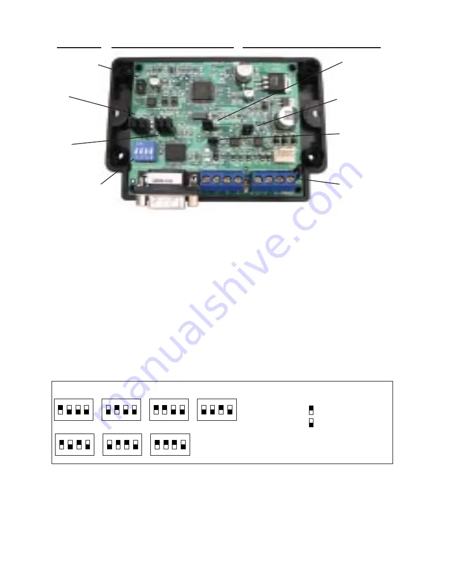
RS-232 (DB9) 9 Pin
Partner Port
INSTALL UNIT * SET ADDRESS AND OPTION JUMPERS * ACTIVATE M1 BUS ENROLLMENT PROCESS
RS-485
M1 Data Bus
RS-485
Partner Port
Data Bus
Address
Switches
Jumpers
S1,S2,S3 select
BAUD rate
Jumpers
S4,S5,S6,S7,S8
select Interface
MODE
J1 -Factory
Use ONLY!
JP3 - Jumper selects
between RS-232 or
RS-485
JP5 - Jumper Selects
+12VDC to DB9 Pin 4
(MUST be in-place for
HAI Thermostats)
JP1 - Jumper selects
termination of M1
RS-485 Data Bus
JP2 - Jumper selects
termination of
other Mfg. RS-485
Table 1: Data Bus Address Switch Settings
ON
1 2 3 4
ON
1 2 3 4
ON
1 2 3 4
ON
1 2 3 4
Address 1
ON
1 2 3 4
ON
1 2 3 4
ON
1 2 3 4
Address 2
Address 3
Address 4
Address 5
Address 6
Address 7
LEGEND
ON
OFF
M1XSP Data Bus Terminating Jumper
JP1 Used to engage a 120 Ohm resistor for
terminating the M1 RS-485 Data Bus. See
Data bus wiring instructions before use.
For an M1XSP the only valid Data Bus
Addresses are 1 thru 7 since the max.
number of M1XSPs is 7.


