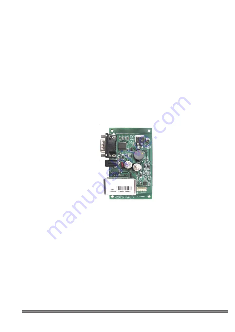
ELK-M1XEP Installation Manual
Page 5
Installation and Hookup
The following connections are required for the M1XEP Ethernet Interface.
a. The DB9M 9-pin male connector should be connected to the DB9F 9-pin female serial port (port 0) on the
Control using a standard 9-pin male to female serial cable (included). The M1Gold has the main serial port
(port 0) on board, while the M1EZ8 requires the M1EZ8MSI Main Serial Interface to provide the port 0
connection. The M1XEP should be mounted within 10 feet of the Control. The baud rate of the Control's
serial port must be set to 115,200, which is the factory default.
b. The 2.1mm barrel type connector is used to connect an ELK-P1216 Plug-in Power Adapter (included). The
M1XEP operates from 12 Volts DC and draws approximately 300 mA. The center pin of the barrel connector
is positive.
d.
1. Remove power from the Control before making any connections.
2. Connect the serial port cable from the Control to the M1XEP. Connect a network patch cable from the M1XEP to
the LAN (local area network) switch or router. Power up the Control.
3. Connect the power cable from the P1216 plug-in power supply. Plug the P1216 into a 110V power outlet. The
M1XEP should power up and attempt to link up with the Ethernet network.
4. Enroll the M1XEP into the Control. Using the keypad, access the Installation Programming menu (Menu 9).
Choose Bus Module Enrollment (Menu 1) and press the right arrow key to start the enrollment. When the enroll-
ment is complete press the ELK or * (Asterisk) key to exit.
Any required network equipment, i.e. Ethernet switch, router, cable modem, etc. including
the plug-in power supply for the M1XEP,
MUST
be backed up with an adequately sized UPS
(Uninterruptible Power Supply) in order for the equipment to continue operating during brief
power outages.
c. The RJ45 8-pin network jack is used to connect the M1XEP to a LAN/WAN Ethernet network switch or router.
This requires a standard network 8-pin RJ45 terminated patch cable (not included).
d. The 5-pin connector along the side of the M1XEP is provided for future use. An ELK-WO35A cable is
required (not supplied) to connect to it. DO NOT CONNECT anything to this connector at this time.
4. Proceed to the Configuration and Setup.
The M1XEP does not connect to the RS-485 data bus on the control, therefore it will not appear
in the list of devices enrolled on the keypad. However, the enrollment process is necessary to
ensure proper supervision of the device. If the M1XEP is removed, it must be "un-enrolled" by
completing the Bus Module Enrollment process to prevent an "Ethernet Trouble" from occurring.
ElkRP versions 1.6.2 and later will display the current firmware, hardware, and bootware versions
of the M1XEP on the " Show KPs and Expanders" screen. This screen is accessed from the Send/
Rcv menu when connected to the control.
a.
b.
c.
All manuals and user guides at all-guides.com


