2
EWPC 961 1/2001 eng
oF = compressor OFF in case of probe de-
fect.
PS
: Protection System-short cycle.
Select type of compressor protection de-
sired (the actual time delay is set with the
next parameter):
0 = delay before start - in seconds;
1 = delay before start - in minutes;
2 = delay after stop - in minutes;
3 = delay between starts - in minutes.
Pt
: Protection time.
Time delay setting for compressor short-
cycle protection; expressed in seconds (0
to 31) if PS = 0 or in minutes (0 to 31) if PS
> 0 (see parameter PS ).
dS
: defrost System (computation).
dF = digifrost
®
Feature; defrost start time is
based on total compressor running time.
rt = real time; defrost initiation frequency is
based on real time.
Time between defrost starts is always the
same.
dI
: defrost Interval.
Defrost start frequency in hours; the time is
calculated based on the selection of para-
meter “dS”.
dE
: defrost Endurance.
Total (maximum) length of a defrost cycle,
expressed in minutes.
dL
: display Lock.
Temperature display is locked in during a
defrost cycle.
n = no (read-out will continue to display the
actual temperature, even during defrost);
y = yes (read-out is locked in).
dr
: display read-out.
Select the type of visualization in case of
temperature display lock during defrost
(see parameter “dL”).
C = the temperature displayed at the start
of a defrost is locked in and does not
change during this cycle.
dF = during the defrost the label “dF”
(deFrost) is displayed to indicate a defrost
is in progress.
do
: defrost at (power) on.
Selects whether the system should go
through a defrost cycle at start-up (or after
a power failure).
n = no;
y = yes.
dd
: defrost delay at (power) on.
Time delay of defrost at (power) on; ex-
pressed in minutes.
INSTALLATION
The instrument is designed for flush panel
mounting. Insert the unit through a
71x29 mm panel cut-out and affix with the
U-bracket supplied. The ambient tempera-
ture around the instrument should be kept
between –5 and 65 °C (23…149 °F).
Select a location which will not be subject
to high humidity or condensation and allow
some ventilation to provide cooling to the
instrument.
ELECTRICAL WIRING
The instrument is equipped with an internal
screw terminal block suitable for max
2.5 mm
2
wiring (one wire each terminal
only).
Make sure that the power supply corre-
sponds with the rating shown on the in-
strument, i.e. 12 V
a
/
c
±15% (VDE/UL
version) or 24 V
a
/
c
±15%.
The 2-wire PTC type probe does not re-
quire polarity and can easily be extended
by using common 2-lead wire.
It is strongly recommended to run the
probe cable separate from line voltage
wiring. Also, it is good practice to install the
tip of the probe in upright position, to avoid
moist from entering into the stainless steel
sensor housing.
The output relay contacts are voltage-free
and are suitable for in-line switching of
compressors up to 0.5 HP at 220 V
a
(or
0.25 HP to 110 V
a
). For larger loads, an
external contactor must be used.
ERROR ANNOUNCIATION
The instrument is provided with only one
error message “E1”, both in case of short-
ed sensor and in case of sensor break, or
sensor absence. The “E1” error message
also appears in the event of underrange of
the system temperature (–55).
In the event of overrange of the system
temperature (99), the “99” value will blink
first, then the “E1” error message will be
displayed in case the probe will exceed the
value of 150
TECHNICAL DATA
Housing
: black ABS plastic, self-estin-
guishing.
Dimensions
: front 74x32 mm
(2.913x1.260"), depth 67 mm (2.637").
Mounting
: flush panel mount with mount-
ing bracket.
Protection
: the instrument frontpanel is
waterproof IP65; an optional snap-on cov-
er can be supplied to provide additional
protection of the rear terminal block.
Connections
: screw terminal block
EWPC 961
1
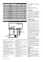
6 7 8 9
thermostat
PTC probe
compressor
POWER SUPPLY
5
3
DEFAULT SETTINGS - STANDARD MODELS
Parameter
d
LS
HS
CA
rP
PS
Pt
dS
dI
dE
dL
dr
do
dd
Description
differential
Lower set
Higher set
CAlibration
relay Protection
Protection System
Protection time
defrost System
defrost Interval
defrost Endurance
display Lock
defrost read-out
defrost at (power) on
defrost delay at (power) on
Range
1…15
–55…99
–55…99
–15…15
on / oF
0…3
0…31
dF / rt
0…31
1…99
n / y
C / dF
n / y
0…99
Default
2
–55
99
0
oF
0
0
rt
8
15
y
C
n
0
Unit
°C / °F
°C / °F
°C / °F
°C / °F
flag
number
seconds
flag
hours
minutes
flag
flag
flag
minutes
CONNECTIONS


