Rev.052114-JA
2
www.elitescreens.com
NOTE:
This equipment has been tested and found to comply with the limits for a Class B digital device, pursuant to
Part 15 of the FCC Rules.
These limits are designed to provide reasonable protection against harmful interference in a residential
installation. This equipment generates and can radiate radio frequency energy and, if not installed and used
in accordance with the instructions, may cause harmful interference to radio communications.
However, there is no guarantee that the interference will not occur on a particular installation. If this
equipment causes harmful interference to radio or television reception, which can be determined by turning
the equipment off and on, the user is encouraged to try to correct the interference by one or more of the
following measures.
Reorient or relocate the receiving antenna of the device which may be causing the
interference.
Increase the separation between the screen and the device’s receiver.
Connect the equipment into a different power outlet other than the device.
Pre-Installation
1.
Carefully unpack the screen.
2.
Always handle the screen in a leveled position on a clean surface.
3.
In order to protect the screen’s viewing surface, do not allow contact with foreign objects such as
dust, writing utensils, liquids, etc.
NOTE
Regardless of the mounting method, the screen should be securely supported so that the vibration or
pulling on the viewing surface will not cause the casing to become loose from the wall and fall to the
ground. The installer must ensure that the fasteners used are of adequate strength and suitable for the
installation location.
Installation
A. Wall Mount (flushed):
1.
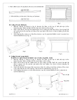
Measure distance A (shown in Fig. 1) between the 2 holes on the backside of both end caps with a
measuring tape. Mark and then drill the two screw holes on the wall.
2.
Insert wall anchors into the two drilled holes on the wall and then insert the screws into the anchors
leaving the screw head to stick out of the anchor by at least a 1/8” (see Fig. 2).
3.
After hanging the screen on to the affixed screws, use the provided bubble leveler to ensure for a
levelled installation (see Fig. 3).
The screw head should
be at least 1/8” away
from the wall
.
Fig.1
Fig. 2
Side view


