


Rev.041014-JA
www.elitescreens.com
6
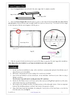
Center Support Bar
d
1.
Insert the
support joiner
into each end of the center support bar to complete assembly.
support joiner
Center support bar
2.
Insert the
Center Support Bar
into the upper top groove on the back of the frame
(not the one where the fix
plate inserts)
with the bottom end near the approximate center point as shown in Fig. 17 and rotate it in at an angle
so that both ends of the bar are in alignment with the groove.
3.
Slide the top end of the bar into the top center point of the frame to complete the center support bar installation.
This will provide added stability to your frame and added tension to the material.
Installation
1.
Locate your desired installation location with a stud finder (recommended) and mark the drill-hole area of
where the screen is to be installed.
2.
Drill a hole with the proper bit size according to the wood screws included.
3.
Line up the wall brackets with the drilled holes on the installation location and screw them in using a
Phillips screwdriver.
Note: Use use 3 top wall brackets on diagonal sizes 135” and above.
4.
Position the fixed frame screen onto the top wall brackets as shown in
(Fig. 19)
and push down at the center
of the bottom frame to secure the installation.
5.
The design of the wall brackets allows the frame to slide over them through its sides. This is an important
feature of the installation design as it allows your screen to be properly centered.
6.
Using both hands finish the installation by pushing the lower portion of the fixed frame screen into the
lower bracket as shown in
Fig 20
.
Center Support Bars
(Fig. 17)
push
Remove
Tension Rod
Center Support Bar


