

V021417-EA
9
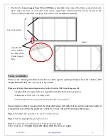
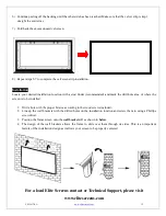
1.
Position the
Corner support bars (N)
and
M6 Hex screws (G)
in the areas of the frame as shown below in
fig 2. Align the holes on each end of the corner support bars with the M6 hex screws located on the
vertical and horizontal frame sections. Then fasten with the
M6x12 screws (I
).
Notice to Installer:
Please use the following installation instructions to obtain superior optical performance from the CineGrey 3D®
Angular Reflective ALR
(Ambient Light Rejecting)
Screen.
Make sure to follow these instructions in order for the CineGrey 3D® to perform correctly.
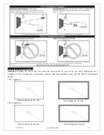
•Angular-Reflective material is not compatible with ultra/short-throw projectors
•Minimum lens throw ratio 1.5x image width
•Ambient light must not come from the same direction as the projector
Since angular-reflective means that the projected image will reflect at the mirror-opposite angle, it
is important to position the projector so that the viewer will get the best possible image.
Step 1:
Establish the general “eye level” of the viewers
Step 2:
Set the appropriate projection level
Step 3:
Adjust the screen height level and projection angle
Input Angle
(A) = Output Angle (B) aligns with the viewer’s angle
Figure 2
Corner Support Bar
Align the M6
screws with the
two holes on the
Corner Support
Bars.