background image

10

ASSEMBLY INSTRUCTIONS

#104  6mm Allen key 105#Screwdriver(1 pcs)

STEP 6


Attach Handlebar (#6) to the Front Post (#10). Ensure the Front Post Cover (#11) has been 

placed over the Handlebar before the Handlebar is secured. Secure using 2 x M8 Bolts (#12), 2 

x Spring Washers (#13) and 2 x Flat Washers (#15). Refer to the above diagram.

Содержание VAlOR 4

Страница 1: ...ASSEMBLY MANUAL Record serial number Elite Valor 4 Elliptical ...

Страница 2: ... this manual to familiarise yourself with the operation of your new Elite Valor 4 Elliptical Doing so will help to insure that you get the most out of your machine enjoying a safe and effective workouts ahead Even though we go to great efforts to ensure the quality of each product we produce occasional errors and or omissions do occur In any event should you find this product to have either a defe...

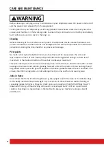
Страница 3: ... all the loose parts before this equipment is used Keeps hands away from moving parts Keep children and pets away from the machine at all time DO NOT leave children unattended in the same room with the machine Before using the machine to exercise always do stretching exercises to properly warm up Inspect the machine before each use make sure all of the connections are tightly secured Only one pers...

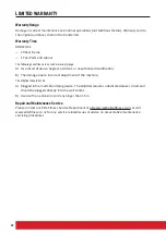
Страница 4: ...by or through the use of this product SERVICE HINTS The high quality standard of this product only will be kept if you on a regular basis check all screw connections and moving parts on proper fitting Damaged parts have to be changed immediately During the time of repair the product must not be used by anybody IMPORTANT HINTS A This product has been tested in accordance with the requirements of EN...

Страница 5: ... indicated in diagrams to carry out the assembly process STEP 1 Attach the Front Stabiliser 59 to the Main frame 89 using 2 x M8 Bolts 55 2 x Semi circle Washers 23 and 2 x Spring Washers 56 Attach the Rear Stabiliser 102 to the Main frame 89 using 2 x M8 Bolts 55 2 x Semi circle Washers 23 and 2 x Spring Washers 56 ...

Страница 6: ...ke y STEP 2 Slide the Front Post Cover 60 over the Front Post 10 Connect the Main Frame Cable to the Front Post Cable Connect the Front Post 10 to the Main Frame 89 using 4 x M8 Bolts 31 4 X Semi circle Washers 32 and 4 x Spring Washers 33 ...

Страница 7: ... Bolt 29 Attach the bottom end of the Lower Handlebar L 34 to the left hand side of the Main Frame 89 using a Nylon nut 37 and Flat Washer 38 on the inner side and a Axle Bush 39 and M8 Bolt 40 on the outer side Attach the top end of the Lower Handlebar R 34 to the right hand side of the Front Post 10 using 1 x Wave Washer 108 1 x Flat Washer 28 1 x Spring Washer 25 and 1 x M8 Bolt 29 Attach the b...

Страница 8: ... Washers 47 and 2 x Nylon nuts 46 Attach the right Pedal 65R to the Right Pedal Arm 66 using 2 x Carriage Bolts 44 2 x Flat Washers 45 2 x Spring Washers 47 and 2 x Nylon nuts 46 Attach the Left Lower arm Covers 41 36 to the Left Pedal Arm 43 using 2 x M5 Screw 4 and 2 x ST2 Screw 42 Attach the Right Lower Arm Covers 41 36 to the Right Pedal Arm 66 using 2 x M5 Screw 4 and 2 x ST2 Screw 42 ...

Страница 9: ...LY MANUAL ASSEMBLY INSTRUCTIONS 104 6mm Allen ke y 105 Screwdr iver 1 pcs STEP 5 Attach the Left and Right Upper Handlebars 21 63 using 4 x M8 Bolts 24 4 x Semi circle Washers 23 and 4 x Nylon Nuts 22 Refer to the diagram above ...

Страница 10: ...ver 1 pcs STEP 6 Attach Handlebar 6 to the Front Post 10 Ensure the Front Post Cover 11 has been placed over the Handlebar before the Handlebar is secured Secure using 2 x M8 Bolts 12 2 x Spring Washers 13 and 2 x Flat Washers 15 Refer to the above diagram ...

Страница 11: ...EP 7 Connect Upper Computer Wire from Computer 1 to the Front Post Wire Connect Upper Pulse Wire from Computer 1 to the Lower Pulse Wire from Handlebar Attach Computer 1 to the Front Post 10 using 4 x M5 Screws 5 Refer to the above diagram 105 Screwdriver 1 pcs ...

Страница 12: ...Handle Bar 34 using 4 screws Attach the right covers 64 62 to right Lower Handle Bar 34 using 4 screws Attach the central covers 17 14 tot he Front Post 10 using 2 M5 Screws 4 Attach the Back Computer Cover 2 to the back of the Computer 1 using 2 Screws 3 105 Screwdriver 1 pcs ...

Страница 13: ...e sure to fully inspect your machine before using it for the first time Failure to visually check and test and tech the assembly before use can cause damage to the Elite Elliptical and serious injury to users and bystanders and can also compromise the effectiveness of your exercise program ASSEMBLY INSTRUCTIONS ...

Страница 14: ...ICK START RECOVERY PULSE HRC DISTANCE DISPLAY FUNCTION VALUE ENTER AND UP DOWN SCAN Alternates between WATTS CALORIES and RPM SPEED 6 seconds per display RPM 0 15 999 SPEED 0 0 99 9 km h TIME 0 00 99 59 DISTANCE 0 00 99 99 km CALORIES 0 999 PULSE P 30 240 HEART SYMBOL ON OFF flashes MANUAL 1 24 level PROGRAM P1 P12 WATTS CONSTANT 10 350 ...

Страница 15: ... a short peroid of time TEST RECOVERY Press RECOVERY the computer will calculate your recovery value and will display the results This uses your preset data and actual workout function value FUNCTION DESCRIPTION MANUAL Set the resistance level using the dot matrix display then if required set exercise parameters TIME DISTANCE CALORIES PULSE then press START STOP to START manual program PROGRAM 12 ...

Страница 16: ...0 AGE 30 39 AGE 40 49 AGE 50 MALE DISTANCE 3 2KM 3KM 2 8KM 2 6KM F5 SPEED 16KM 15KM 14KM 13KM FEMALE DISTANCE 3KM 2 8KM 2 4KM 2 2KM SPEED 15KM 14KM 12KM 11KM MALE DISTANCE 3 2 4KM 3 3 38KM 2 8 3 4KM 2 6 3 2KM F4 SPEED 20KM 19KM 17KM 16KM FEMAILE DISTANCE 3 3 6KM 2 8 3 4KM 2 4 3KM 2 2 2 8KM SPEED 18KM 17KM 15KM 14KM MALE DISTANCE 4 4 8KM 3 8 4 6KM 3 4 4 2KM 3 2 4KM F3 SPEED 24KM 23KM 21KM 20KM FEMA...

Страница 17: ...ght window press ENTER key to confirm Function Control display will flash indicating you can select the Programs P1 P12 by turning UP DOWN key and then press ENTER key to confirm Any of the default values can be changed by pushing the ENTER key until the desired program profile is flashing Press the ENTER key to confirm When the Program and other protocols are entered press START STOP key and begi...

Страница 18: ...ints need to be tightened enough so there is still movement in the desired direction of travel but no sideways movement Excessive sideways movement causes knocking noises and extra wear Crosstrainers with a sealed bearing on the axle do not require greasing however units with a plastic or brass bushing should be greased twice a year with general purpose automotive grease between the axle and bush ...

Страница 19: ...ic maintenance checks Not only does this ensure your machine is in full working order but it will save you service costs in the long run Every time you perform maintenance record the date and if you can the distance and hours operated DATE HOURS DISTANCE FRAME SERVICE COMMENTS Cleaned Joints 01 06 15 16 5km none ...

Страница 20: ...ion B The damage due to incorrect adjustment of the machine The Elliptical should not be A Plugged into a multi board plug device The elliptical requires a dedicated power circuit and should be plugged directly into the wall socket B Used with an extension cord any longer than 1 5m Repair and Maintenance Service Please contact our Elite Fitness Service Department at eliteservice elitefitness co nz...

Страница 21: ...s Hold for 10 15 seconds and relax Repeat 3 times for each leg See picture 2 Crus and Feet Tendon Stretches Standing with two hands on the wall or tree one leg behind Keeping your legs straight and the heel on the ground lean forward towards the wall or tree Hold for 10 15 seconds and relax Repeat 3 times for each leg See picture 3 Quadriceps Stretches Keeping your balance with your left hand hold...

Страница 22: ...adial wrist or carotid neck pulse using your index and middle fingers counting the beats for 10 seconds and multiplying by 6 Alternatively the use of a Wireless Telemetry Heart Rate strap and watch will give you an accurate Beats Per Minute BPM reading 220 AGE TMHR Theoretical Maximum Heart Rate TMHR x 85 Upper Training Limit bpm Beats per Minute TMHR x 65 Lower Training Limit bpm Note Contact hea...

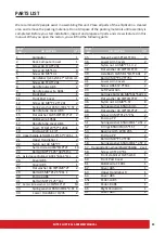
Страница 23: ...nut A3 M8 7T 4 23 Semi circle A3 Ф8 Ф19 2T 14 24 Bolt A3 M8 P1 25 38L S15L 4 25 Axle sleeve PA Mos2 φ38 1 φ16 9 31L 2 26 Cover ABS 1 27 Cover ABS 1 28 Flat washer A3 Ф8 Ф28 2T 2 29 Bolt ABS M8 P1 25 20L 1 30 End cap ABS 1 31 Bolt A3 M8 P1 25 16L 6 32 Semi circle washer A3 Ф8 Ф19 2T 14 33 Spring washer 65Mn Ф8 1 2 5T 6 34 Lower Handlebar Q235 2 35 Sleeve Fe φ31 8 φ15 10L 4 36 Lower Arm Covers 2 37 ...

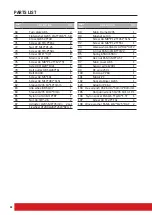
Страница 24: ... Sleeve Q235 1014 3mm 1 85 Nylon nut A3 M10 8T 1 86 Nut A3 3 8 26 2 87 Adjuster Q235 M6 35m m 2set 88 Flywheel HT200 φ280 26W 6KG 1 89 Main Frame Q235 1 90 Magnet set A3 1 91 Screw A3 M8 P1 25 45L S15L 2 92 Screw A3 M6 P1 25 55L 1 93 Wave washer 65Mn Ф20 5 Ф30 0 3T2 94 C rings 65Mn Ф18 5 Ф22 2 95 Spring 65Mn 65Mn 1 96 Hex nut 65Mn M6 4 5T 1 97 Main cover ABS 1 98 Sensor wire 1200L 1 99 DC wire 250...

Страница 25: ...25 ELITE ELLIPTICAL ASSEMBLY MANUAL EXPLODED DRAWING 6mm All en key 1 pcs Screwdriver 1 pcs ...

Страница 26: ...26 EXPLODED DRAWING ...

Страница 27: ...27 ELITE ELLIPTICAL ASSEMBLY MANUAL NOTES ...

Страница 28: ... visit www elitefitness co nz Copyright 2015 Elite Fitness Elite Fitness 11 George Bourke Drive Mt Wellington Auckland New Zealand 0800 243 834 www elitefitness co nz Keep up to date with the latest products competitions and equipment follow us on our social media sites EliteFitnessNZ EliteFitnessTV ...

Отзывы: