background image

9

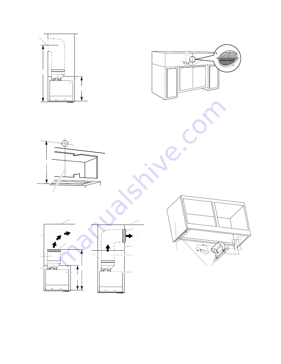
Venting outside through the wall

Measure from the bottom of the range hood liner to the 

horizontal centerline of the vent opening (A)�

A

B

C

D

A.  Measurement A

B.  Horizontal centerline of vent opening

C.  Range hood liner

D.  12” (30.5 cm) min. cabinet height

Remove the vent duct from the range hood liner� Transfer 

measurement A to the cabinet back wall� Measure from 

the underside of the cabinet�

Mark the cutout as shown� Use a saber saw or keyhole saw 

to cut a round opening through the back of the cabinet 

and the exterior wall for the vent� 

A

B

C

A.  Measurement A

B.  Centerline

C.  6¼” (15.9 cm) round 

cutout

Non-vented (recirculating) installation through the soffit/

cabinet

E

A

B

G

D

F

H

I

A

B

G

F

C

D

E

A.  Ceiling

B.  Vent cover

C.  Soffit

D.  6” (15.2 cm) vent

E.  Range hood

A.  Cabinet Wall

B.  12” (30.5 cm) min. cabinet height

C.  17” (43.2 cm) min. vent cover height

Measure and mark the centerline of the cabinet to the 

soffit above�

Measure from the bottom of the cabinet to the centerline 

of the where the vent will come through the soffit� Mark 

the location and use a saber saw or keyhole saw to cut a 

5¾” (14�6 cm) hole for the vent cover�

A

B

A�  Vent cover

B�  Centerline

*

NOTE

: For 12” (30�5 cm) high cabinets a 6¼” deep x 8” wide 

(14�6 cm x 20�3 cm) rectangular opening in the cabinet top is 
required for damper transition clearance�

Consider the cutout chart measures to make the openings 

on the cabinet�

Complete preparation

If not yet attached, install the 6” (15�2 cm) vent transition 

the top of the range hood liner using two 3�5 x 9�5 mm 

screws�

Locate side mounting bracket flush 1 cm to the bottom of 

the cabinet side and against the inside of the front cabinet 

face� Orient the bracket depending on the width of your 

cabinet as depicted in the diagrams below� Drill 1⁄8” (3 

mm) pilot holes in 6 places, attach a bracket using three 

4�5 x 13 mm screws to each side of the cabinet, and tigh-

ten� Additional washers in hardware package are supplied 

as spacers for cabinet walls thinner than ½”(13 mm)�

Bracket Orientation for 30” (76�2 cm) Cabinet

A

B

C

D

A.  30” (76.2 cm) cabinet

B.  Screws - 4.5 x 13 mm (8)

C.  Washers (optional)

D.  Mounting bracket (2) (position for 30” [76.2 cm] cabinet) 

Содержание ASTI EAS428S2

Страница 1: ...d utilisation d entretien et d installation Guía de instalación uso y mantenimiento READ AND SAVE THESE INSTRUCTIONS LISEZ CES INSTRUCTIONS ET CONSERVEZ LES LEA Y CONSERVE ESTAS INSTRUCCIONES LIB0178769 Printed in Mexico 11 21 Models EAS428S2 ...

Страница 2: ...ce 12 Accesories 13 Warranty 14 ENGLISH Contents APPROVED FOR RESIDENTIAL APPLIANCES FOR RESIDENTIAL USE ONLY READ AND SAVE THESE INSTRUCTIONS PLEASE READ ENTIRE INSTRUCTIONS BEFORE PROCEEDING INSTALLATION MUST COMPLY WITH ALL LOCAL CODES IMPORTANT Save these Instructions for the Local Electrical Inspector s use INSTALLER Please leave these Instructions with this unit for the owner OWNER Please re...

Страница 3: ...ce IWARNING TO REDUCE THE RISK OF A RANGE TOP GREASE FIRE a Never leave surface units unattended at high settings Boilovers cause smoking and greasy spillovers that may ignite Heat oils slowly on low or medium settings b Always turn hood ON when cooking at high heat or when flambeing food I e Crepes Suzette Cherries Jubilee Peppercorn Beef Flambe c Clean ventilating fans frequently Grease should n...

Страница 4: ...oviding an escape wire for the electric current This range hood is equipped with a cord having a grounding wire with a grounding plug The plug must be plugged into an outlet that is properly installed and grounded WARNING Improper grounding can result in a risk of electric shock Consult a qualified electrician if the grounding instructions are not completely understood or if doubt exists as to whe...

Страница 5: ... will be installed must be sealed For mobile home installations The installation of this range hood must conform to the Manufactured Home Construction Safety Standards Title 24 CFR Part 328 formerly the Federal Standard for Mobile Home Construction and Safety title 24 HUD Part 280 or when such standard is not applicable the standard for Manufactured Home Installation 1982 Manufactured Home Sites C...

Страница 6: ...t depth is greater than 12 2 4 5x13 mm 8 3 5x9 5 mm 6 4 2x15 mm 2 Torx 10 adapter 1 3 5x9 5 mm 4 Ø 6 4x18 mm washers 8 4 2x19 mm 8 Ø 6 4x18 mm washers 8 Parts not supplied Tools Materials required Level Drill with 1 3 2 cm 1 8 3 2 mm y 1 16 4 8 mm drill bits Pencil Pliers Tape measure or ruler Caulking gun and weatherproof caulking compound Saber or keyhole saw Metal snips Vent clamps Screwdrivers...

Страница 7: ...ittings material is provided to secure the hood to most types of walls ceilings However a qualified technician must verify suitability of the materials in accordance with the type of wall ceiling Before making cutouts make sure there is proper clearance within the ceiling or wall for exhaust vent I CAUTION For gas cooktop range installations Mount the hood so the bottom is at least 30 76 2 cm abov...

Страница 8: ...1 8 66 3 cm 107 8 27 62cm 3 4 1 9 cm 1 2 1 27 cm A Bottom of cabinet cutout 2 Complete cabinet preparation following the instructions for your type of venting Determine venting cutout loca tions and cut out vent openings in the cabinets walls and or soffit Venting outside through the roof 1 Measure and mark the lines as shown Use a saber saw or keyhole saw to cut an opening through the top of the ...

Страница 9: ...line of the where the vent will come through the soffit Mark the location and use a saber saw or keyhole saw to cut a 5 14 6 cm hole for the vent cover A B A Vent cover B Centerline NOTE For 12 30 5 cm high cabinets a 6 deep x 8 wide 14 6 cm x 20 3 cm rectangular opening in the cabinet top is required for damper transition clearance 3 Consider the cutout chart measures to make the openings on the ...

Страница 10: ...in the cabinet Align the bottom of the canopy with the bottom of the cabinet Install four 4 2 x 19 mm screws into the hood canopy assembly and tighten all 8 mounting screws A C B A Cabinet B Hood liner canopy assembly C Screws 4 2 x 19 mm 8 3 Remove the metal grease filters from the face panel 4 Connect the lamps connector to the connector present inside the hood as shown in drawing A B A Lamp con...

Страница 11: ...e hood is designed to remove smoke cooking vapors and odors from the cooktop area For best results start the hood before cooking and allow it to operate several minutes after the cooking is complete to clear all smoke and odors from the kitchen The hood controls are located on the center of the front of the range hood liner A B C D A Blower and light controls B Grease filter handle C Grease filter...

Страница 12: ...local inspector that this hoods maximum airflow has been reduced to 300 CFM Indicators of filter saturation At regular time intervals the hood indicates the need of performing filter maintenance Blower button icon blink no edge Perform grease filter maintenance Light button blink no edge Perform activated charcoal filter maintenance Reset of filter saturation indicators With blower Off press and h...

Страница 13: ...Wall C 12 30 5 cm min cabinet height D 17 43 2 cm min vent cover height NOTE 12 30 5 cm high cabinets without a soffit may allow the 6 vent and vent cover to be seen 1 Cover the grill that protects the suction motor with the carbon filter so that the slots on the filter correspond to the pins on the sides of the motor protection grill 2 Turn the carbon filter clockwise to block them bayonet fixing...

Страница 14: ...d for ordinary residential use in North America Including the United States Guam Puerto Rico US Virgin Islands Canada This warranty is non transferable and applies only to the original purchaser and does not extend to subsequent owners of the product This warranty is made expressly in lieu of all other warranties expressed or implied including but not limited to any implied warranty of merchantabi...

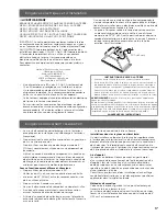
Страница 15: ...ouvoir vous y référer plus tard Avertissement de sécurité Coupez l alimentation du circuit dans le panneau électrique et verrouillez le panneau avant de raccorder les fils de cet appareil Exigence 120 V c a 60 Hz circuit de dérivation de 15 V c a 20 Hz de 15 ou 20 A Avis de Sécurité Important 16 Exigences électriques et d installation 17 Exigences Concernant l évacuation 17 Dimensions du Produit 1...

Страница 16: ...trique avant la maintenance I AVERTISSEMENT POUR RÉDUIRE LES RISQUES D INCENDIE DE GRAISSE SUR LES CUISINIÈRES a Ne laissez jamais la cuisinière sans surveillance lorsqu elle est réglée à une haute température Les débordements par bouillonnement causent de la fumée et des débordements de gras qui peuvent s enflammer Faites chauffer l huile lentement à une température basse ou moyenne b Faites touj...

Страница 17: ...RTISSEMENT Une mise à la terre incorrecte peut entraîner un risque de choc électrique Consulter un électricien qualifié si les instructions de mise à la terre ne sont pas complètement comprises ou si vous avez des doutes quant à la qualité de la liaison à la terre de la hotte Ne pas utiliser de câble de rallonge Si le cordon d alimentation électrique est trop court faire installer une prise près d...

Страница 18: ...sinière Installation dans une résidence mobile L installation de cette hotte doit satisfaire aux exigences de la norme Manufactured Home Construction Safety Standards Titre 24 CFR partie 328 anciennement Federal Standard for Mobile Home Cons truction and Safety titre 24 HUD partie 280 lorsque cette norme n est pas applicable l installation doit satisfaire aux critères de la plus récente édition de...

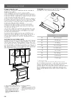
Страница 19: ...5 mm 2 Adaptateur Torx 10 1 3 5x9 5 mm 4 Rondelles Ø 6 4x18 mm 8 4 2x19 mm 8 Rondelles Ø 6 4x18 mm 8 Pièces non Fournies Outils nécessaires Niveau Perceuse avec forets de 1 3 2 cm 1 8 3 2 mm y 1 16 4 8 mm Crayon Pince à dénuder ou couteau utilitaire Mètre ruban ou règle Pince Pistolet à calfeutrage et composé de calfeutrage résistant aux intempéries Brides de conduit Scie sauteuse ou scie à guiche...

Страница 20: ...s une solive ou un montant à moins qu il soit absolument nécessaire de le faire Si vous devez couper une solive ou un montant vous devez construire un cadre de soutien La quincaillerie fournie permet de fixer la hotte à la plupart des murs et des plafonds Vous devez cependant demander à un technicien qualifié de vérifier la solidité des matériaux selon le type de mur ou de plafond Avant de couper ...

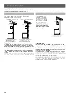
Страница 21: ...pour certains types de placards Ouverture dimensions sans barres d espacement 261 8 66 3 cm 107 8 27 62 cm 3 4 1 9 cm 1 2 1 27 cm A Ouverture dans le fond du placard 2 Terminer la préparation du placard conformément aux instructions correspondant au type d évacuation du domicile Déterminer l emplacement des ouvertures d aération et découper les ouvertures dans les placards les murs et ou les soffi...

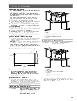
Страница 22: ...ance entre le bas du placard et l axe central au point où le conduit d évacuation ressort du soffite Indiquer l emplacement et utiliser une scie sauteuse ou scie à guichet pour découper un trou de 5 14 6 cm pour le cache conduit A B A Cache conduit B Axe central REMARQUE Pour les placards d une hauteur de 12 30 5 cm une ouverture rectangulaire de 6 de profondeur x 8 de largeur 14 6 cm x 20 3 cm da...

Страница 23: ...E DU POIDS EXCESSIF UTILISER DEUX OU PLUS DE PERSONNES POUR DÉPLACER ET INSTALLER LA HOTTE DE LA CUISINIÈRE LE NON RESPECT DE CETTE INSTRUCTION PEUT CAUSER UNE BLESSURE AU DOS OU D AUTRE BLESSURE 1 À l aide d au moins 2 personnes soulever la caisse de la hotte et l installer La fixer dans les encoches en forme de trou de serrure à l aide de quatre vis Phillips n 2 de 4 2 x 19 mm Ne pas serrer les ...

Страница 24: ...PAS ENLEVER LA BROCHE DE LIAISON À LA TERRE NE PAS UTILISER UN ADAPTATEUR NE PAS UTILISER UN CÂBLE DE RALLONGE LE NON RESPECT DE CES INSTRUCTIONS PEUT CAUSER UN DÉCÈS UN INCENDIE OU UN CHOC ÉLECTRIQUE 2 Brancher le cordon d alimentation à 3 broches dans la prise à 3 alvéoles reliée à la terre située dans le placard qui se trouve au dessus de la hotte 3 Contrôler le fonctionnement du ventilateur de...

Страница 25: ...nés la hotte reproduit chaque son Lorsque la sourdine est sélectionnée le coin supérieur gauche du bouton lumineux s allume en rouge Pour régler le son choisissez en un et appuyez sur les deux boutons en même temps Système de Réduction CFM Avant d utiliser votre hotte Certains États et certaines provinces des États Unis et du Canada limitent le le débit d air maximum des hottes de cuisine Le débit...

Страница 26: ...er le filtre en tirant sur la poignée à ressort puis en tirant le filtre vers le bas A A Poignée à ressort 2 Laver le filtre métallique selon le besoin au lave vaisselle ou avec une solution de détergent chaude 3 Réinstaller le filtre en s assurant que les poignées à ressort sont orientées vers l avant Insérer le filtre à graisse métallique dans la rainure supérieure 4 Tirer sur la poignée à resso...

Страница 27: ...osez le filtre à charbon comme couverture de la grille qui protège le moteur aspirant de manière que les fentes présentes sur le filtre correspondent aux pivots sur les côtés de la grille protège moteur 2 Tournez le filtre à charbon dans le sens des aiguilles d une montre pour le bloquer fixation à baïonnette Les filtres à charbon ne peuvent pas être nettoyés Il doit être remplacé tous les 4 6 moi...

Страница 28: ...un usage domestique habituel en Amérique du Nord Y compris Etats Unis Guam Porto Rico les Iles virgin Américaines le Canada Cette garantie n est pas transférable et vaut uniquement pour l acheteur original et ne s étend pas aux propriétaires successifs du produit Cette garantie vaut expressément en lieu et place de toute autre garantie expresse ou sous entendue mais ne limite pas toute autre garan...

Страница 29: ...desbloquee el panel Requisito Circuito auxiliar de 120 V AC 60 Hz 15 ó 20 A CAMPANA PURIFICADORA Marca ELICA Modelos EAS428S2 Contenido 1 pza Hecho en México Fabricado por ELICAMEX S A de C V Dirección Av La Noria No 102 int S N Col Parque Industrial Querétaro Del Santiago de Querétaro C P 76220 Querétaro R F C EII060102RK8 Aviso de Seguridad Importante 30 Requisitos eléctricos y de instalación 31...

Страница 30: ...ontrol de la velocidad I ADVERTENCIA La mala colocación de los tornillos o artefactos de montaje o sujeción de acuerdo a estas instrucciones puede traer consigo peligros eléctricos I ADVERTENCIA PARA REDUCIR EL RIESGO DE INCENDIO OCASIONADO POR GRASA a No deje nunca ninguna unidad externa desatendida y con valores de fuego altos La cocción puede causar humo o reboses de grasa que pueden prender fu...

Страница 31: ...dos para el tamaño del elemento de la superficie Este aparato no se destina para utilizarse por personas incluyendo niños cuyas capacidades físicas sensoriales o mentales sean diferentes o estén reducidas o carezcan de experiencia o conocimiento a menos que dichas personas reciban supervisión o capacitación del funcionamiento del aparato por una persona responsable de su seguridad Los niños deben ...

Страница 32: ... y el número de codos se deben mantener Para obtener el funcionamiento más eficaz y silencioso No use más de 3 codos de 90 Asegúrese de que haya un mínimo de 24 61 cm de ducto de escape recto entre los codos si se utiliza más de 1 codo No instale 2 codos lado a lado El sistema de ventilación debe tener una compuerta Use abrazaderas para sellar todas las juntas en el sistema de ventilación Utilice ...

Страница 33: ...stalación en casas rodantes Estándar de seguridad y construcción de casas fabricadas Título 24 CFR Parte 328 anteriormente conocido como Federal Standard for Mobile Home Construction and Safety Estándar federal para la seguridad y construcción de casas rodantes Título 24 HUD Parte 280 o cuando dicho estándar no sea aplicable el estándar Manufactured Home Installation Instalación en casas fabricada...

Страница 34: ...yor a 12 2 4 5x13 mm 8 3 5x9 5 mm 6 4 2x15 mm 2 Adaptador Torx 10 1 3 5x9 5 mm 4 Rondana de Ø 6 4x18 mm 8 4 2x19 mm 8 Rondana de Ø 6 4x18 mm 8 Piezas no suministradas Herramientas Materiales necesarios Nivel Taladro con brocas de 1 3 2 cm 1 8 3 2 mm y 1 16 4 8 mm Lápiz Pelacables o cuchillo de uso general Cinta de medir o regla Pinzas Pistola para calafateo y masilla para calafateo a prueba de agu...

Страница 35: ... fuera necesario efectuar el corte deberá construirse un marco de soporte Se suministra el material de ajuste necesario para fijar la campana a la mayoría de tipos de muro o techo No obstante un técnico cualificado debe comprobar la idoneidad de los materiales de acuerdo con el tipo de muro o techo Antes de efectuar algún corte asegúrese de que existe el espacio libre adecuado en el techo o muro p...

Страница 36: ...7 cm A Corte inferior de gabinete 2 Complete la preparación del gabinete siguiendo las instrucciones para el tipo de ventilación que ha elegido Determine los cortes para el ducto de ventilación en el gabinete pared o techo Ventilación hacia el exterior a través del techo 1 Mida y marque las líneas como se muestra Use una sierra para hacer una apertura a través de la cara superior del gabinete y el...

Страница 37: ...se del armario hasta la línea central de donde el ducto de escape atravesará el sofito Marque la ubicación y use una sierra de vaivén o caladora para cortar un orificio de 5 14 6 cm para la cubierta del ducto Sujete la cubierta del ducto de escape con dos tornillos de 4 5 x 13 mm A B A Cubierta del ducto B Línea central NOTA Para gabinetes con altura de 12 30 5 cm se necesita una abertura rectangu...

Страница 38: ...priete los tornillos 2 Centre la campana al gabinete Mantenga alineados la cara inferior del gabinete con el borde inferior del gabinete Inserte cuatro tornillos de 4 2 x 19 mm en las aberturas redondas de la placa de montaje y apriete todos los tornillos de montaje 8 A C B A Gabinete B Ensamble de la campana C 8 tornillos 4 2 x 19 mm 3 Remueva los filtros metálicos de grasa del panel frontal 4 Re...

Страница 39: ...e ha disparado un cortacircuitos o si se ha quemado un fusible doméstico Desconecte el suministro eléctrico y revise las conexiones de cableado NOTA Para obtener un uso más eficaz de su nueva campana de cocina lea la sección Descripción de la campana Descripción de la Campana A B C D A Botones de luz y motor B Manija del filtro de grasa C filtro de grasa D Luces LED Control A B A Botón de la luz B...

Страница 40: ...o de aire máximo a 300 CFM Localice la pegatina de certificación de CFM en el paquete de hardware Este adhesivo proporciona una certificación oficial a su inspector local de que el flujo de aire máximo de esta campana se ha reducido a 300 CFM Indicadores de saturación del filtro A intervalos regulares la campana indica la necesidad de realizar el mantenimiento del filtro El icono del botón del sop...

Страница 41: ...un técnico de servicio Vea la sección A quién contactar para la información de contacto del servicio Lámpara LED empotrable Potencia asignada 2 x 2 1 W Potencia máxima 2 5 W Tensión asignada 3 V Tipo de socket n a Dimensiones Ø 67mm x 20mm Accesorios Kit Recirculante Si no es posible ventilar los humos y vapores de cocina al exterior la campana puede ser usada en su versión filtrante recirculante ...

Страница 42: ... QUIÉN ESTÁ CUBIERTO Esta garantía se extiende al comprador original de productos adquiridos para uso residencial en Norte América incluyendo Estados Unidos Guam Puerto Rico Islas Vírgenes de EU y Canadá Esta garantía no es transferible y aplica solamente al comprador original y no se extiende a propietarios subsecuentes del producto Esta garantía se expresa en lugar de otras garantías expresadas ...

Страница 43: ...43 ...

Страница 44: ...44 ...

Отзывы: