
►
For units with protection class IP 44, the customer con-
nection of the cable ends or connector (cable bushing)
must also be carried out in accordance with protection
class IP 44.
Damage to the Venetian blind from incorrect running direc-
tion
►
The assignment of the running direction UP/DOWN with
an elero radio transmitter must be reviewed after teach-
ing.
Adjustment of the end position at the drive.
►
Any adjustment of the end positions that occurs indicates
an electrical connection error. Readjustment of the end
positions is not suf
fi
cient in this case, since the end
positions are adjusted often. In this case, the drive needs
to be replaced and the cause removed.
Important
All applicable standards and provisions must be observed
for the electrical installation.
When connecting the drive to a control, the operating
instructions of the control must be observed.
For electric connection no transmission and retransmission
of the access line or connector is required as a rule.
Depending on the mounting plate and/or adapter plate
used it is necessary in particular with the RolTop /D+ 868 to
remove this screwed plate before a cable exchange.
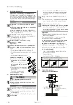
Connection only in free of tension status, in addition
drive line without tension
1
Using a suitable screwdriver, press out the lock of the
device connector to the line.
2
Disconnect the plug.
3
Insert connector until the latch engages.
Removal and insertion of the device plug
Delivery status Remove plug
Insert plug
Fig. 4 Removal and insertion of the device plug
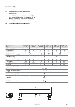
5.3 Connection
example,
RolTop /D+ 868 230 V/50 Hz
N
PE
L1
sw
br
bl
gr
/g
e
→
1
→
2
→
3
1
Winding thermostat
2
Device plug
3
Junction box
(outside of roller shutter case)
4
Electronics
5
Capacitor
sw
black
br
brown
bl
blue
gr/ge
green yellow
4 | EN
©
elero
GmbH
Mechanical fastening
5.1 Mechanical
fastening
Important preliminary consideration:
The working space around the built-in drive is usually very
small. Therefore, before the mechanical installation provide
an overview of the implementation of the electrical connec-
tion (see Section 5.2) and make any necessary changes
right away.
NOTICE
Damage to the electrical wiring by squeezing or tensile
loading.
►
Route all electrical cables so that they are not subjected
to crushing or tensile load.
►
Note the bending radius of the cables (at least 50 mm).
►
Lay the connection cable in a loop downwards to prevent
water running into the drive.
Damage to the drive by the action of impact forces.
►
Insert the drive into the shaft, never thrust the drive into
the shaft or smash onto the drive!
►
Never allow the drive to fall!
Damage or destruction of the drive by drilling.
►
Never drill into the drive!
Important
Attach the RolTop /D + 868 only at the intended fasteners.
Permanently installed control devices shall be clearly dis-
played.
• The curtain must be fastened to the winding shaft.
• The pro
fi
le tube must have enough distance to the motor
tube.
• Look for an axial clearance (1-2 mm).
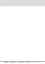
Installation in pro
fi
le tubes
Ⓐ
Insert the drive with a suitable adapt-
er and traction ring into the pro
fi
le
tube.
Lay the motor cable protected in or-
der to prevent damage by the driven
component.
Ⓑ
Secure the counter bearings against
axial displacement, e.g. screw shaft
spider or rivet.
Secure drive in axial storage!
Ⓒ
Secure hanging on the shaft!
5.2 Electrical
connection
WARNING
Danger to life due to faulty electrical connection.
Electric shock possible.
►
Before commissioning check the correct connection of
the PE conductor.
NOTICE
Damage to the RolTop /D + 868 by faulty electrical connec-
tion
►
Before commissioning check the correct connection of
the PE conductor.
Damage or destruction of RolTop /D + 868 by the penetra-
tion of moisture
B
A
C


