background image

-2-

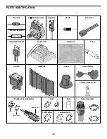
PARTS IDENTIFICATION

Resistor

2k

Ω

Potentiometer

Capacitor

Diode

Transistor

Integrated Circuit

Transformer

PC Board

Fuse

Heatsink

Switch

Knob

Strain Relief

PC Board Stand-off

Binding Post Assembly

Fuse Assembly

Flat Washer

Lockwashers

Mica

Nuts

7mm

6-32 / 8-32

#8

5/16”

Binding Post

Lockwasher

Nut

.18

Ω

3W Resistor

Содержание XP-720K

Страница 1: ...opyright 2007 1998 by Elenco Electronics Inc All rights reserved Revised 2007 REV D 753269 No part of this book shall be reproduced by any means electronic photocopying or otherwise without written permission from the publisher Elenco Electronics Inc ...

Страница 2: ... 512013 1 Fuse 1A 530100 1 Rocker Switch 541204 1 Cover 611120 1 Chassis 612012 1 Heat Sink 615010 2 Knob 622009 1 Strain Relief 624003 5 Insulator Washer 624007 4 PC Board Stand off 625001 2 Black Binding Post 625031 7 Int Lockwasher Binding Post 625031LW 7 Nut Binding Post 625031HN 2 Red Binding Post 625032 3 Yellow Binding Post 625034 5 Screw 6 32 x 3 8 Phillips Pan Machine 641640 2 Screw 8 32 ...

Страница 3: ...citor Diode Transistor Integrated Circuit Transformer PC Board Fuse Heatsink Switch Knob Strain Relief PC Board Stand off Binding Post Assembly Fuse Assembly Flat Washer Lockwashers Mica Nuts 7mm 6 32 8 32 8 5 16 Binding Post Lockwasher Nut 18Ω 3W Resistor ...

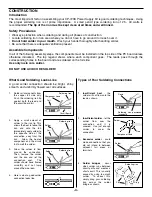
Страница 4: ...t times to signify a decimal point as in 3R3 3 3 103K 100V The letter M indicates a tolerance of 20 The letter K indicates a tolerance of 10 The letter J indicates a tolerance of 5 Maximum Working Voltage The value is 10 x 1 000 10 000pF or 01μF 100V Electrolytic capacitors have a positive and a negative electrode The negative lead is indicated on the packaging by a stripe with minus signs and pos...

Страница 5: ...ad Solder Soldering Iron Drag Foil 1 Solder all components from the copper foil side only Push the soldering iron tip against both the lead and the circuit board foil 2 Apply a small amount of solder to the iron tip This allows the heat to leave the iron and onto the foil Immediately apply solder to the opposite side of the connection away from the iron Allow the heated component and the circuit f...

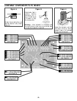
Страница 6: ...hown on the top legend Leave 1 4 between the part and PC board Band D5 1N5400 Diode D6 1N5400 Diode D7 1N5400 Diode D8 1N5400 Diode see Figure A C1 10μF Electrolytic C2 10μF Electrolytic C3 10μF Electrolytic C4 10μF Electrolytic C8 10μF Electrolytic see Figure B C7 4700μF Electrolytic see Figure B Q1 A70 Transistor see Figure C D4 1N4001 Diode D3 1N4001 Diode D2 1N4001 Diode D1 1N4001 Diode see Fi...

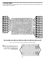
Страница 7: ... 4 Red Hole K 4 Orange Hole J 3 Red Hole I 4 Blue Hole H 3 Orange Hole G 4 Blue Hole F 4 Red Hole E 6 Blue Hole D 4 Red Hole C 3 1 2 Red Hole W 3 Orange Hole V 3 1 2 Blue Hole U 3 Blue Hole T 3 1 2 Orange Hole S 3 Red Hole R 4 1 2 Blue Hole Q 5 Orange Hole P 4 1 2 Red Hole O 5 Blue Hole N 4 1 2 Orange Hole M 5 Red Hole L Peel off the protective paper from the bottom of the rubber feet and apply on...

Страница 8: ...m nut Turn both potentiometer shafts all the way counter clockwise Line up the line on the knobs with the first line on the voltage scale Press knobs onto the shaft of the potentiometers Note the lug configuration on the rocker switch Push the switch into the hole in the chassis with lug 1 on top as shown in Figure D PANEL ASSEMBLY Figure D Lug 1 Lockwasher Nut Black Red Black Yellow Rocker Switch...

Страница 9: ...sulation off the end of all two end wires to expose 1 4 of bare wire Insert 6 of the line cord into the bottom hole on the back of the chassis as shown in Figure G Place the line cord into the slot of the strain relief and squeeze the two sections together with pliers Then insert the strain relief into the hole Install the transformer with the black wires side as shown in Figure I Use an 8 32 x 3 ...

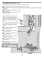
Страница 10: ...ush the PC board down in place WIRING LINE CORD FUSE TRANSFORMER AND SWITCH Figure I Install the line cord ground lug to the chassis using a 6 32 x 3 8 screw and a 6 32 large nut in the location shown in Figure I Strip the insulation off of both ends of the 6 red 20 ga wire to expose 1 4 of bare wire Solder one end of the wire to lug 3 on the rocker switch as shown in Figure I Slip the other end o...

Страница 11: ...o place Tin the leads Form the end of the wires into a tight loop for easy tight connection to leads before you apply solder 3 1 2 Red wire W from PC board To middle lead of LM 317 3 1 2 Orange wire S from PC board To left lead of LM 317 3 1 2 Blue wire U from PC board To right lead of LM 317 3 Red wire R from PC board To middle lead of LM 337 3 Blue wire T from PC board To left lead of LM 337 3 O...

Страница 12: ...ire M from PC board to right lead of LM 7805 After wiring be sure that the leads do not touch each other and cause a short Solder the wires from the PC board to the potentiometers as shown in Figure L 4 Red wire E from PC board to middle lug of the positive voltage pot 4 Blue wire F from PC board to right lug on the positive voltage pot 4 Orange wire J from PC board to middle lug on the negative v...

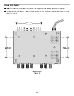
Страница 13: ...x 3 8 black pan head screws as shown in Figure M Fit the cover onto the chassis Fasten in place with two 6 x 3 8 black truss head screws on each side as shown in Figure M Bottom View Figure M 6 x 3 8 Pan Head Screws 6 x 3 8 Truss Head Screws 6 x 3 8 Truss Head Screws ...

Страница 14: ... Output Voltage 1 Check the AC voltage at anode of D1 It should read about 17VAC If not check the fuse transformer ON OFF switch or line cord 2 Measure voltage at output of D1 It should read about 20VDC If not check D1 D3 and C5 3 If 20V is OK check IC1 No Negative Voltage Output 1 Check the voltage at the output of D4 It should be 20VDC Check D2 D4 and C6 and make sure that they are not in backwa...

Страница 15: ...ction The arrow in Figure 3 points to the direction that the current will flow Only when the transformer voltage is positive will current flow through the diodes Figure 3 shows the simplest possible rectifier circuit This circuit is known as a half wave rectifier Here the diode conducts only half of the time when the AC wave is positive as shown in Figure 2C Use of this circuit is simple but ineff...

Страница 16: ...se is connected to a stable 1 5V reference voltage The base of Q2 is connected to the regulator output circuit through a voltage divider network The collector of transistor Q2 is connected to a current source This basically is a PNP transistor biased to draw about 1mA of current Transistor Q2 sees the current source as a very high resistor of about 1 meg ohms Thus the gain of transistor Q2 is extr...

Страница 17: ...or Q2 takes over and delivers the current to the output Note that if the output voltage goes down the LM 7805 regulator will draw more current forcing the output voltage back to 5V Thus the LM 7805 regulator controls the output voltage and keeps it at 5V Unfortunately this circuit has no control of the output maximum current If the output is shorted to ground transistor Q2 will be overloaded and e...

Страница 18: ...l value capacitor with a high voltage value C Large value capacitor D 90O out of phase rectification circuit 6 An inefficient rectification circuit usually contains A large gaps between cycles B twice the AC voltage needed C more diodes D all of the above 7 The maximum current that a diode can handle is determined by A the transformer s current rating B the amount of AC ripple C three times the di...

Страница 19: ... 1A 3 5VDC 3A 4 6 3 12 6CTAC 1A Output Regulation 200mV each supply Line Regulation 100mV each supply Ripple Max 5mV rms Current Protection Thermal overload 15VDC Current limiting 5VDC Fuse 6 3VAC Short Protection Current limiting 5VDC 15VDC Fuse 6 3VAC Output Impedance 2Ω 15VDC 06Ω 5VDC 18 SCHEMATIC DIAGRAM Maximum output individually rated ...

Страница 20: ...Elenco Electronics Inc 150 Carpenter Avenue Wheeling IL 60090 847 541 3800 Web site www elenco com e mail elenco elenco com ...

Отзывы: