


-9-
CALIBRATION
Refer to the METER OPERATION section for test lead connections and measurement procedure.
A/D CONVERTER CALIBRATION
Turn the range selector switch to the 20V position and connect the test leads. Using another meter of known accuracy,
measure a DC voltage of less than 20 volts (such as a 9V battery). Calibrate the kit meter by measuring the same voltage
and adjusting VR1 until the kit meter reads the same as the accurate meter (do not use the kit meter to measure its own
battery). When the two meters agree, the kit meter is calibrated. Turn the knob to the OFF position and remove the voltage
source.
SHUNT WIRE CALIBRATION
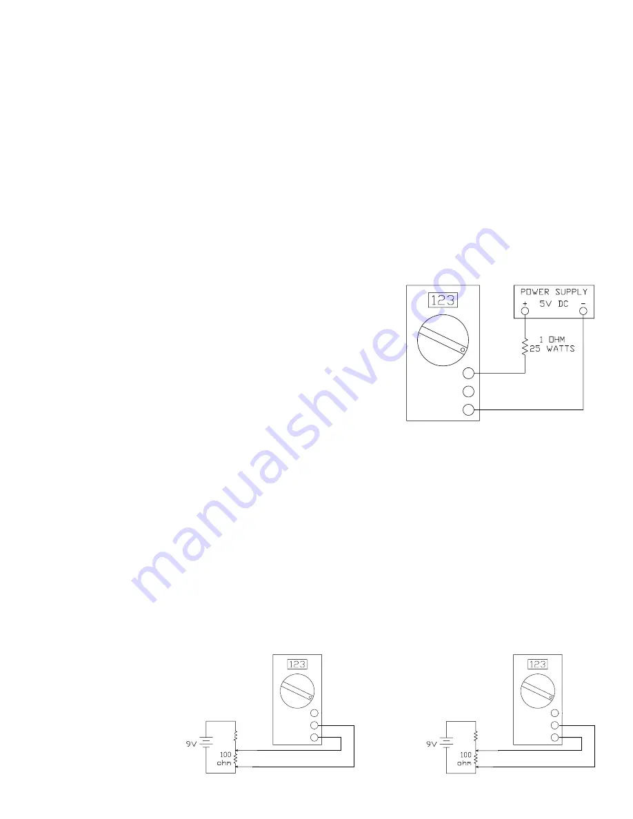
To calibrate the shunt wire, you will need a 5 amp current source such as a
5V power supply and a 1 ohm, 25 watt resistor. If a 5 amp source is not
available, you can use a lower current (2 amps). If no supply is available, it is
not important to do this test. Set the range switch to the 10A position and
connect the test leads as shown in Figure 5-1. If the meter reads higher than
5A, resolder the shunt wire so that there is less wire between the 10A DC and
COM sockets.
If the meter reads low, resolder the shunt wire so that there is more wire
between the sockets.
If the calibration fails:
a) Check the PC board for solder bridges and bad solder connections.
b) Check that Q1 is installed according to Figure 4-2 of the assembly instructions.
c)
Check the values of resistor R10 - R13, R26, and potentiometer VR1.
DC VOLTS TEST
1) If you have a variable power supply, set the supply to about the midpoint of each of the DCV ranges and compare the
kit meter reading to a meter known accuracy.
2) If you do not have a variable power supply, make the following two tests:
a)
Set the range switch to 2000mV and measure the voltage across the 100 ohm resistor of Figure 5-2A. You should
get about 820mV. Compare the reading to a meter of known accuracy.
b)
Set the range switch to 200mV and measure the voltage across the 100 ohm resistor of Figure 5-2B. You should
get about 90mV. Compare the reading to a meter of known accuracy.
If any of these tests fail:
a) Recheck the meter calibration.
b) Check the value and the soldering
of resistors R1-R6, R16.
Figure 5-2A
Figure 5-2B
Figure 5-1
If any of these tests fail:
a) Check that the battery is good.
b) Check that IC1 is installed according to Figure 4-2 of the assembly instructions. Check for bent pins that do not extend
into the IC socket. Check for good contact between the leads of the IC and the pins of the socket.
c)
Check the values of resistors R14, R15, R19, R20, R23 - R25.
d) Check the values of capacitors C1 - C5.
e) Check that Q2 is installed according to Figure 4-1 of the assembly instructions.
f)
Check the PC board for solder bridges and bad solder connections.
g) Check that the slide contactors are seated correctly.
h) Check that the LCD and zebras are seated correctly.
1k ohm
10k ohm
10ADC
V
Ω
MA
COM
10ADC
V
Ω
MA
COM
10ADC
V
Ω
MA
COM


