2 0
Appendix A
I N S T A L L A T I O N M A N U A L |
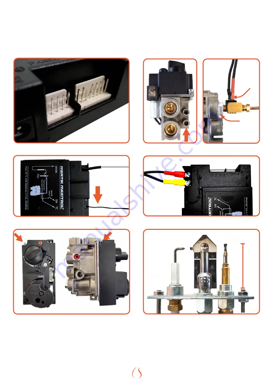
Figure A.A |
Bend pin
Figure A.B |
Antenna
Figure A.C |
Torx screw
Figure A.D |
Testpoint
4,5 mV
Figure A.E |
Interrupter
Figure A.F |
Wiring receiver
40mm
Figure A.G |
Pilot set
Страница 1: ...INSTALLATI O N MA NUAL INSTALLATI O N MA NUAL Please leave these instructions behind with the device K U D O S...
Страница 2: ...INSTALLATION MANUAL i Do not use this product as a primary heat source...
Страница 3: ...G WALLS 7 6 FIRE SAFE INSTALLATION 8 6 1 FIRE SAFETY DEVICE SET UP 8 6 1 1 PROTECTION OF WALL AND CEILING 8 6 2 ASSEMBLY REGULATIONS WITH FLAMMABLE MATERIALS 8 6 2 1 FLOOR PROTECTION 8 6 2 2 RADIATION...
Страница 4: ...ORS CODES PROCONTROL APP 24 B A MESSAGES SHOWN IN APP 24 B B MESSAGES SHOWN IN REMOTE 25 C FAULTS AND ERROR CODES IN THE REMOTE 26 C A F41 ERROR 26 C B ROUTER INFORMATION 26 C B A MINIMUM REQUIREMENT...
Страница 5: ...ke sure it is accessible at all times This device may not be used a primary heat source This device is designed to be used with natural gas or LPG The device can only be used with the type of gas spec...
Страница 6: ...sembly error or material defect Element4 will provide a free replacement part to the installer without compensation for disassembly or montage 5 In case the installer is not able to fix the problem hi...
Страница 7: ...ON 1 2 OFF Figure 3 1 Remote and ignition sign Figure 3 2 Gas Block Figure 3 3 Top and side view of the Receiver 4 2 IGNITING THE PILOT LIGHT Check that the control knob A is in the ON position Figur...
Страница 8: ...e in the near vicinity of the device Position the gas connection such that it is always accessible for service purposes The gas block and receiver are under the combustion chamber in the deivce so tha...
Страница 9: ...contain flammable building materials and all walls on which flammable objects e g built in furniture or wooden panels are mounted on the side of the wall that is turned away from the fireplace Walls c...
Страница 10: ...ombustible materials Top A a a H G Figure 6 1 Distances to combustible materials front B A a a C E D Figure 6 2 Floor plate Letter Minimum Distance to flammable materials mm A 120 B 350 C 300 D 600 E...
Страница 11: ...ach category refers to a set of tables 1 A table for horizontal outlet 2 A table for vertical outlet You must use the table applicable to you You calculate your total vertical section TVS as well as y...
Страница 12: ...L Follow the following instrucions for the installation of flue materials Drill a hole of 160 mm for the wall or roof transit In a situtation of non combustible materials keep a distance of at least 5...
Страница 13: ...vice for a period of one week to ensure yourself of an optimal desired room temperature Also the device can changed between high and low flames and it features an eco setting The amount of users that...
Страница 14: ...e test points on the gas valve can be reached and the relevant button can also be reached for a reset of the receiver 9 3 THE COMBUSTION CHAMBER The glass must be removed to enter the combustion chamb...
Страница 15: ...NSTALLATION MANUAL Figure 9 2 Front view after glass removal Figure 9 3 Gas control in brackets under fireplace Figure 9 4 Hooks on windows 1 2 Figure 9 5 Removal of front frame 1 2 Figure 9 1 Positio...
Страница 16: ...this is the case check the burner pressure at the inlet to the burner The instructions of changing the burner pressure and the correct pressure per gastype can be found in 9 6 2 PILOT The pilot flame...
Страница 17: ...peration of the appliance 10 DECORATIVE CERAMIC PARTS This appliance is equipped with a ceramic fire bed with heat resistant ceramic fibers or artificial glassy silicate fibers Excessive exposure to t...
Страница 18: ...rid and place the indicated logs in the correct place on the grid For the rest of the logs it is important that the grate is not too full If necessary adjust the position of the decoration material if...
Страница 19: ...ble plus button to switch between burners Flames and soot During this first fire examine the flame for appearance and quality Flames may appear blue at first but will turn yellow after 15 to 20 minute...
Страница 20: ...turbs the reception Change the position of the antenna See Figure A B C No ignition no beep 1 Receiver defective Reset the receiver See K1 If necessary replace the receiver D No ignition receiver give...
Страница 21: ...Appendix A INSTALLATION MANUAL Figure A A Bend pin Figure A B Antenna Figure A C Torx screw Figure A D Testpoint 4 5 mV 4 5 mV Figure A E Interrupter Figure A F Wiring receiver 40mm Figure A G Pilot s...
Страница 22: ...ouple Position burner grate 3 Airflow in the burner chamber causes a restless fire image Check drain configuration Fit a flue gas limiter I Receiver gives 3 short beeps after each command 1 Batteries...
Страница 23: ...Aux position receiver AM PM ON 1 2 OFF Figure A L Double plus button on the remote Figure A M SI port PANEL G60 ZCE 1000 MA GR MO SW 2 1 3 MODE Ignition Main Burner High Flames Pilot Extinguish Main...
Страница 24: ...ed Please note If a problem is found that cannot be solved on site always contact your dealer or directly contact Element4 via our credentials which can be found on the back page of this manual 00 00...
Страница 25: ...eeps for 3 sec during motor turn Low Receiver battery power supply F10 Contact Service Pilot lit Main burner fails to ignite and pilot shuts off Ignition is blocked for 2 minutes 2nd thermocouple is o...
Страница 26: ...mmunication between Receiver and myfire Wi Fi Box F44 Contact Service No temperature shown in App N a not applicable displayed in App Handset not within range Low battery power in handset F49 Contact...
Страница 27: ...istances from occurring Many people put the router in the meter cupboard because that is where the internet comes in at many households A bad choice For a powerful WiFi signal the router needs as much...
Страница 28: ...NAL LOCATION WITH VERTICAL EXHAUST C11 Distance Exhaust 1 2 of 3 At the same roof level 6m At a different roof level 3m On a lower wall 2m On a higher sloping surface 6m Distance minimum distance requ...
Страница 29: ...O O V V 6 O O O O O O V V 5 O O O O O O V V 4 O O O O O O V V 3 5 O O O O O O V V 3 V V V V V V V V 2 5 V V V V V V V V 2 V V V V V V V V 1 5 V V V V V V V X 1 V V V V V X X X 0 5 X V V X X X X X 0 1...
Страница 30: ...ner 1x 140 FlatBurner 2x 160 LogBurner 1x 120 FlatBurner Type of flue C11 C31 C91 Additional electricity use At rated heat output elmax 9 5 kW With minimal heat emission elmin 9 5 kW In standby mode e...
Страница 31: ...longs to G A ECOLABELS The ecolabels for the different types of gas are indicated below respectively G20 G25 and G30 From 2022 the UKCA label is used for the United Kingdom Both versions may be found...
Страница 32: ...awings of the fireplace with some of the important dimensions that you have to take into account when installing and installing your fireplace 710 50 704 00 350 00 270 00 80 00 550 00 19 00 588 00 483...
Страница 33: ...Info element4 nl www element4 nl 19 01 22 ELEMENT 4 B V Design Assembly by RELEASE DATE...