background image

Page 16 of 24                                                                                                                                  M6493 Issue 10.3 


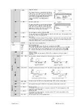
1IT 

0..999s 

Integral action time. 
 
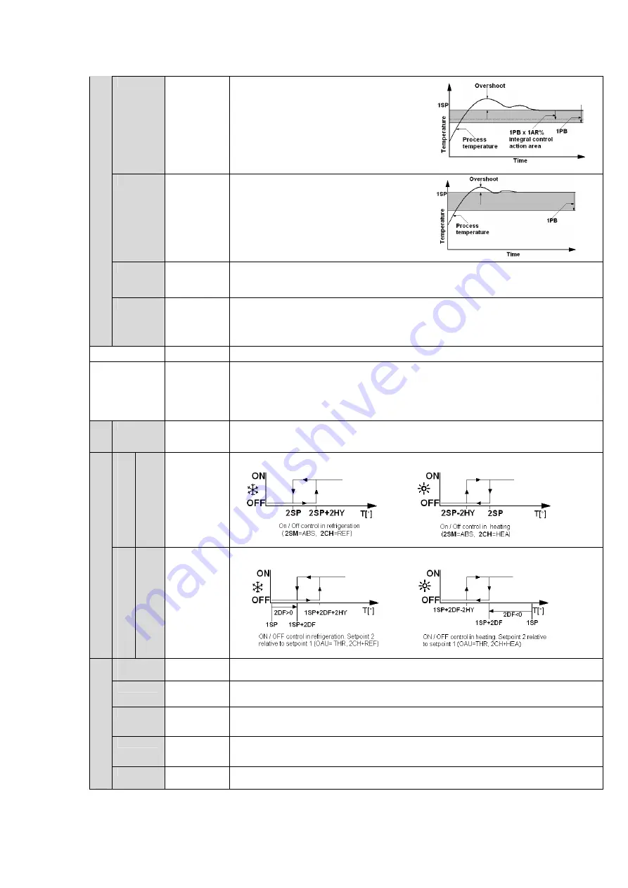
The steady-state error is cancelled by inserting an 
integral action. The integral action time, determines 
the speed with which the steady-state temperature 
is achieved, but a high speed (

1IT 

low) may be the 

cause of the overshoot and instability in the 
response. With 

1IT

=0 the integral control is 

disabled 


1DT 

0…999s 

Derivative action time 
 
Response overshoot may be reduced by inserting 
a derivative Action. A high derivative action (

1DT


high)  makes  the system very sensitive to small 
temperature variations and causes instability. With 

1DT

=0 the derivative control is disabled. 


1AR 

0..100% 

Reset of integral action time referred to 

1BP


Decreasing the paramater 

1AR

 reduces the integral ontrol action zone, and consequently the 

overshoot (see figure on paragraph 

1IT

).


1CT 

1…255s 

Cycle time. 
It’s the period in which the output ON time changes. The quicker the system to be controlled 
reacts to temperature variations, the smaller the cycle time must be, in order to obtain higher 
temperature stability and less sensativity to load variations. 

1PF 

ON/OFF 

Output state in case of probe failure. 

*OAU 


NON; 
THR; 
AL0; 
AL1 

AUX output operation. 
NON; output disabled (always off).(

the next perameter will be 

ATM).


THR: output programmed for second thermostat control 

(the next parameter will be 

2SM

). 

AL0: contacts open when an alarm condition occurs

 (the next perameter will be 

ATM). 

AL1: contacts make when an alarm condition occurs 

(the next parameter will be 

ATM). 


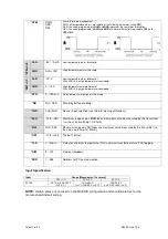
2SM 

ABS; 
REL 

Setpoint 2 mode. 
Channel 2 setpoint may be absoulte (2SM=ABS), o a differential relative to setpoint 1 
(2SM=REL). 

*O

A

U

=

R

EL


2

SM

=

ABS


2SP 

SPL….SPH 

Auxiliary output switchover temperature 

(the next prameter will be 2CH). 


2

SM

=

R

EL


2DF 

-19.9+19.9° 

Temperature differential relative to 1SP. The auxiliary output setpoint is equal to 1SP+2DF 


*O

A

U

=

T

H

R


2CH 


REF; HEA 

Refrigerating control (REF) of heating control mode (HEA) for the auxiliary output. 

2HY 

0…19.9° 

Defferential of thermostat 2. With 2HY=0 the auxiliary output always remains off. 

2T0 

0…30min 

Minimum off time. 
After output 2 has been turned off, it remains inactive for 2T0 minutes reguardless of the 
temperature value measured. 

2T1 

0…30min 

Minimum on time. 
After output 2 has been furned on, it remains active for 2T1 minutes reguardless of the 
temperature value measured. 

2PF 

ON / OFF 

Auxiliary output state in case of probe failure. 

Содержание MC810B MKII

Страница 1: ...Page 1 of 24 M6493 Issue 10 3 MC810B MKII DIGITAL TEMPERATURE CONTROLLER INSTRUCTION BOOK ...

Страница 2: ...aration of Conformity Page 24 Appendix A Decontamination certificate Page 22 The copyright of this instruction book is the property of Bibby Scientific Limited This instruction book is supplied by Bibby Scientific Limited on the express understanding that it is to be used solely for the purpose for which it is supplied It may not be copied used or disclosed to others in whole or part for any purpo...

Страница 3: ...by a plug in platinum resistance probe The sample temperature is displayed on the LED display This product is suitable for bench and retort stand mounting or wall mounting using the bracket and screws provided 1 3 The MC810B has a short mains output lead with an IEC socket to connect it to the resistive load An accessory extension mains lead is available where remote operation is required e g in a...

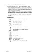
Страница 4: ... should read and be familiar with this Instruction book in order to preserve the protection afforded by the equipment To prevent injury or equipment damage it is the manufacturer s recommendation that all persons using this equipment are suitably trained before use 2 2 Symbols Defined Caution risk of danger See note or adjacent symbol Protective conductor terminal to be earthed Do not loosen or di...

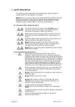
Страница 5: ...e controller whilst power is applied 3 2 General Safe Operating Practice Always follow good laboratory practice when using this equipment Give due recognition to your company s safety and legislative health safety procedures and all associated legislation applicable to your areas of operation Check laboratory procedures for substances being heated and ensure all hazards e g explosion implosion or ...

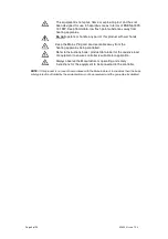
Страница 6: ...Plug and Lead set cable away from the heating apparatus being controlled Refer to Instructions book product data label for the resistive load of equipment to ensure controller is suitable for application Always observe the Manufacturer s operating and safety instructions for the equipment to be connected to the controller NOTE if this product is not used in accordance with the Manufacturer s Instr...

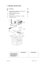
Страница 7: ...moulded IEC plug and lead set May be different from illustration As Req 2 MC810B MKII Digital Controller 1 3 Instruction Book 1 4 Wall fixing Bkt x 1 and screws x 2 per bag 1 5 Temperature Probe 1 For future reference please record your products Serial and Model Numbers Serial Number Model Number ...

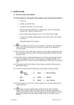
Страница 8: ... fitted See Technical Specification Section 8 of this Instruction book 5 5 Check the voltage on the product data label of this unit Ensure the rating conforms to your local supply Only connect to resistive loads 1500Watts 230V AC or 750Watts 115V AC Refer to Technical Specification Section 8 of this Instruction book 5 6 This product must be connected to a mains supply source which incorporates an ...

Страница 9: ...ormation For end users outside of the EU consult applicable regulations 6 4 This product should only be dismantled for recycling by an authorised recycling company This product and accessories must be accompanied by a completed Decontamination Certificate prior to any disposal Copies of the Certificate are available from your distributor of Bibby Scientific products or you may copy and enlarge fro...

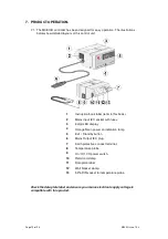
Страница 10: ...ins input IEC socket with fuses 3 3 digit LED display 4 Orange Neon power on indication lamp 5 Exit Standby button 6 Mains Output IEC plug 7 Earth protective conduct terminal 8 Temperature probe 9 On Off I O power switch 10 Retort rod clamp 11 Data plate label 12 Wall bracket clamp 13 5 Pin DIN socket for temperature probe Check the data plate label and ensure your mains electrical supply voltage ...

Страница 11: ...he temperature is anywhere below set point and fully off when the temperature is anywhere above the desired set point 7 3 2 On Off Controller plus Hysteresis To prevent detrimental control chattering as the temperature crosses the set point an On Off differential or hysteresis can be added to the controller function When a hysteresis value is entered for example say 3 C the controller will switch ...

Страница 12: ...nt temperature to be approached relatively smoothly with minimal overshoot 7 4 Front Panel Controls The MC810B controller has four front panel keys as described below 7 4 1 The key is used to increase the value of the parameter shown on the display or to scroll through the parameter menu 7 4 2 The key is used to decrease the value of the parameter shown on the display or to scroll through the para...

Страница 13: ...justment is within the minimum SPL and maximum SPH limit To store the new value press button or wait 10 seconds To return to operational mode without saving the settings press the Exit standby button 7 8 Stand By 7 8 1 Press the button and wait for the 3 seconds The word OFF will be displayed To resume press the button once again for another 3 seconds and the display will return to normal operatio...

Страница 14: ...band Increase 1SP the case of the heating control vice versa decrease 1SP in the case of refrigeration control and re start the process E2 timeout2 error the auto tuning has not ended within the maximum time allowed 1000 cycles Re start the auto tuning process and set a longer cycle time 1CT E3 temperature over range check the error was not caused by a probe malfunction then decrease 1SP in the ca...

Страница 15: ...you select control with hysteresis parameters 1HY 1T0 and 1T1 are used With 1CM PD you select a Proportional Integral Derivative control mode parameters 1PB 1IT 1DT 1AR 1CT will be used 1CH REF HEAS Refrigerating REF or Heating HEA control mode 1CM HY 1HY 0 19 9 C OFF ON thermostat differential With 1HY 0 the output is always off 1TO 0 30min Minimum off time After output 1 has been turned off it r...

Страница 16: ...d variations 1PF ON OFF Output state in case of probe failure OAU NON THR AL0 AL1 AUX output operation NON output disabled always off the next perameter will be ATM THR output programmed for second thermostat control the next parameter will be 2SM AL0 contacts open when an alarm condition occurs the next perameter will be ATM AL1 contacts make when an alarm condition occurs the next parameter will...

Страница 17: ...ore alarm temperature warning SB NO YES Stand by button enabling INP 0mA 4mA Sensor input selection see table of input specifications RLO 19 9 RHI Maximum range values RLO takes the maximum value measured by the transmitter i e the value matching 1V 20mA RHI RLO 99 9 Maximum range vlue RHI takes the maximum value measured by the transmitter i e the value matching 1V 20mA OS1 12 5 12 5 Probe T1 off...

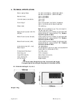
Страница 18: ... Mains Power Lead set Europe 3 core earthed ground 2 meters long Moulded IEC plug and Lead set supply cord H0 V V F Replace only with equivalent cable Mains Power Lead set USA 3 core earthed ground 2 meters long Moulded IEC plug and Lead set supply cord SJT VW 1 Replace only with equivalent cable Lead set plug fuse UK only 13A BSEN1362 Mains Output Non detachable 3 core mains cable with moulded IE...

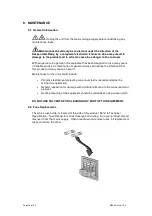
Страница 19: ...reduce the effective life of this product and may cause a hazard Maintenance for the unit should include Periodic electrical safety testing an annual test is recommended as the minimum requirement Regular inspection for damage with particular attention to the mains lead and plug set Routine cleaning of the equipment should be undertaken using a clean cloth DO NOT USE SOLVENTS FOR CLEANING ANY PART...

Страница 20: ...consult Customer Support Refer to section 10 If the equipment has been exposed to contamination the Responsible Body is responsible for carrying out appropriate decontamination If hazardous material has been spilt on or inside the equipment decontamination should only be undertaken under the control of the Responsible Body with due recognition of possible hazards Before using any cleaning or decon...

Страница 21: ...es bibby scientific com Technical support electrothermalhelp bibby scientific com www electrothermal com For the America s and Canada contact Techne Incorporated 3 Terri Lane Suite 10 Burlington NJ 08016 USA Toll free 800 225 9243Tel 609 589 2560 Fax 609 589 2571 Email labproducts techneusa com Http www techneusa com 11 PARTS AND ACCESSORIES AZ9035 Fuse F8A Qty 10 230V AC Product AZ6747 Mains cord...

Страница 22: ...eleting YES NO as applicable and by providing details in section 2 below A Blood body fluids Pathological specimens YES NO Provide details if YES B Biodegradable material that could become a hazard YES NO Provide details if YES C Other biohazard YES NO Provide details if YES D Chemical or substances hazardous to health YES NO Provide details if YES E Radioactive substances State name s and quantit...

Страница 23: ...Page 23 of 24 M6493 Issue 10 3 12 NOTES ...

Страница 24: ...ific Limited Beacon Road Stone Staffordshire ST15 0SA Great Britain Tel 44 0 1785 812121 Fax 44 0 1785 810405 General enquiries info bibby scientific com Order enquiries sales bibby scientific com Technical support electrothermalhelp bibby scientific com www electrothermal com For the America s and Canada contact Techne Incorporated 3 Terri Lane Suite 10 Burlington NJ 08016 USA Toll free 800 225 9...

Отзывы: