2005.11 dmm
51/60
599 37 38-46
6.3.2 Control/display
board
The way in which these boards are fastened depends on the styling version. To access the board:
a. Remove the control panel
b. Release the PCB casing from the control panel or remove the screws.
For further details, refer to the specific Service Manuals for the various types of electronic control systems.
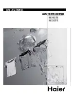
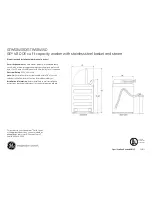
6.3.3 Electronic pressure switch
a. Remove the top.
b. Press down the anchor tabs and release the pressure switch from
the support. (Fig. 10)
c. Detach the connector.
d. Detach the tube.
6.4 Access from the door
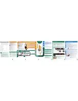
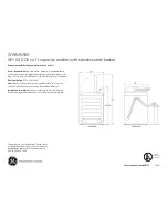
6.4.1 Door
a. Remove the two screws which secure the door to the hinge. (Fig.
11)
b. Remove the screws which secure the surround-flange (if present)
and detach the flange from the surround.
c. Remove the glass door panel.
d. Remove the handle-latch assembly.
Re-assembly:
e. Position the handle assembly in its housing in the flange so that
the spring exerts pressure correctly.
f. Refit the glass panel to the flange.
g. Replace the surround and the screws.
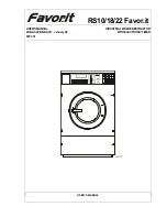
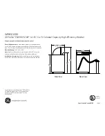
6.4.2 Door hinge
a. Remove the porthole door.
b. Detach the seal front the front panel. (Fig. 12)
c. Remove the screws which secure the hinge to the front panel.
d. Remove
the
hinge.
11
12
10
Содержание Nexus 6000 Series
Страница 2: ...2005 11 dmm 2 60 599 37 38 46 ...