SERVICE MANUAL
WASHING
ELECTROLUX HOME PRODUCTS
ITALY S.p.A.
Spares Operations Italy
Corso Lino Zanussi, 30
Publication
number
I - 33080 PORCIA /PN (ITALY)
599 37 38-46
Fax +39 0434 394096
Edition: 2005.11.03
EN/dmm
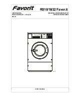
Washing machines
P6000 (Nexus) Series
Structural characteristics,
electrical components and
accessibility
Production: THR
RAYONG- Thailand
Содержание Nexus 6000 Series
Страница 2: ...2005 11 dmm 2 60 599 37 38 46 ...