


60
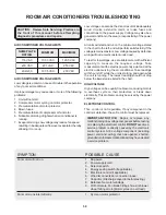
SYMPTON
POSSIBLE CAUSE
Fan motor noisy.
1. Condenser fan blade or evaporator blower
wheel.
2. Loose power clamp or set screw.
3. Worn bearings.
4. Grommets (if applicable).
Compressor will not run, but fan motor runs.
1. Voltage.
2. Wiring.
3. Selector switch.
4. Temperature control.
5. Capacitor. (Discharge capacitor before testing.)
6. Compressor.
7. Motor protector (external).
8. Motor protector (internal).
9. Electronic control (if applicable).
10. Hard starting.
Compressor cycles on motor protector.
1. Voltage.
2. Motor protector (external).
3. Motor protector (internal).
4. Fan motor.
5. Condenser air flow restriction.
6. Condenser fins damanged.
7. Capacitor.
8. Wiring.
9. Refrigerant system.
Insufficient cooling.
1. Low capacity.
2. Air filter.
3. Exhaust door open.
4. Unit undersized.
Excessive noise.
1. Evaporator blower wheel.
2. Condenser wheel.
3. Copper tubing.
4. Compressor internal noise.
5. Fan motor.
Excessive water or condensation.
1. Unit operating under extremely high humidity
conditions.
No cooling.
1. Refrigerant leak.
Unit is cooling but room is not cool.
1. Amps and watts.
2. Sealed refrigeration system.
Wattage decreases slowly until abnormally low.
1. Undercharged, restricted strainer or plugged
restrictor tube.
Wattage decreases immediately.
1. No refrigerant.
2. Compressor defective.
Wattage continuously high.
1. Refrigerant overcharge.
Содержание FAA055P7A-1
Страница 32: ...32 63611621 63611326 ...
Страница 33: ...33 63611618 63611620 ...
Страница 34: ...34 63611619 M1 M2 63611613 ...
Страница 35: ...35 63611329 63611614 ...
Страница 36: ...36 633611615 63611622 ...
Страница 37: ...37 63611616 63611091 ...
Страница 38: ...38 63611642 ...
Страница 39: ...39 63611328 ...
Страница 40: ...40 63611094 63611629 ...
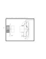
Страница 41: ...Control Thermostat Location diagram for Heavy Duty 41 ...
Страница 42: ...Control Thermostat Location diagram for Median 42 ...
Страница 43: ...Control Thermostat Location diagram for Slider Casement 43 ...
Страница 44: ...Control Thermostat Location diagram for TTW 44 ...
Страница 45: ...The 5th pipe The 4th pipe 160cm Control Thermostat Location diagram for COM2 45 ...
Страница 46: ...The 5th pipe The 4th pipe 130cm Control Thermostat Location diagram for OPP5 46 ...
Страница 47: ...The 5th pipe The 4th pipe 160cm Control Thermostat Location diagram for MS2 47 ...
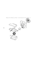
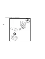
Страница 48: ...Condenser Fan and Evaporator Blower Location Diagram for TTW 1 48 ...
Страница 49: ...Condenser Fan and Evaporator Blower Location Diagram for Slider Casement 1 49 ...
Страница 50: ...Condenser Fan and Evaporator Blower Location Diagram for Heavy Duty 1 50 ...
Страница 51: ...Condenser Fan and Evaporator Blower Location Diagram for Median 1 51 ...
Страница 52: ...Condenser Fan and Evaporator Blower Location Diagram for TTW 2 52 ...
Страница 53: ...Condenser Fan and Evaporator Blower Location Diagram for Slider Casement 2 53 ...
Страница 54: ...Condenser Fan and Evaporator Blower Location Diagram for Median 2 54 ...
Страница 55: ...Condenser Fan and Evaporator Blower Location Diagram for Heavy Duty 2 55 ...
Страница 56: ...Condenser Fan and Evaporator Blower Location Diagram for OPP5 56 ...
Страница 57: ...Condenser Fan and Evaporator Blower Location Diagram for MS2 57 ...
Страница 58: ...Condenser Fan and Evaporator Blower Location Diagram for COM2 58 6cm 8cm ...


