


15
Power Cord Number
Page #
High
Medium
Low
Heat Only
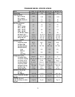
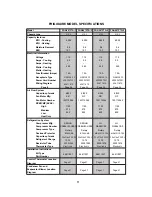
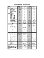
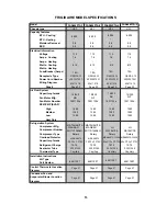
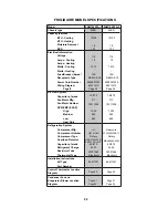
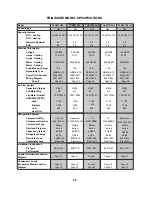
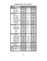
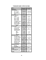
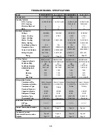
FRIGIDAIRE MODEL SPECIFICATIONS
Model
Chassis type
Capacity features
BTU - Cooling
BTU - Heating
Moisture Removal
EER
Electrical Information
Voltage
Amps - Cooling
Amps - Heating
Watts - Cooling
Watts - Heating
Fuse/Breaker (Amps)
Receptacle Type
Wiring Diagram
Fan Motor Number
RPM/CMP (EVAP)
Air Flow System
Capacitor-µ farads
Fan Motor Mfg.
Refrigeration System
Compressor Mfg.
Compressor Number
Compressor Type
Part Number
Overload Protector
Capacitor-µ farads
Refrigerant Charge
Restrictor Tube
Thermostat Type
Installation Instructions
Kit Type
Diagram
Control Thermostat Location
Diagram
Condenser Fan and
Evaporator Blower Location
FAA087P7A-1
FAA087P7A-4
-
15A
Page 3
4
-
MRA98073-12026
MS 2
MS 2
4002057201
4002057201
63611619
NEM
A
5-15
NEM
A
5-15
NEM
A
5-15
NEM
A
5-15
40/15uF 370V
-
15/250
15/250
15011036
KB
18.34
03001275
115
-
-
15A
Page 3
4
-
Rotary
Rotary
63611619
-
15011036
20.45
03001047
Electronic
LG
8,000
-
0.8
10.8
8,000
-
0.8
10.8
115
740
-
7.1
740
7.1
1480
1380
1280
1480
1380
1280
QA104CCA
FAA087P7A-2
FAA087P7A-5
-
15A
Page 3
4
-
2R11S126A6H
MS 2
MS 2
4002057201
4002057201
63611619
35/15uF 370V
-
15/250
15/250
15011036
NT
115
-
-
15A
Page 3
4
-
Rotary
Rotary
63611619
-
15011036
MATSUSHITA
-WANBAO
MRA98076
8,000
-
0.8
10.8
8,000
-
0.8
10.8
115
740
-
7.1
740
7.1
1480
1380
1280
1480
1380
1280
MATSUSHITA
-WANBAO
2R11S126A6H
35/15uF 370V
MRA98076
18.34
64611007
64611007
64611007
64611007
03001275
Electronic
Electronic
Electronic
20.45
03001047
KB
NT
LG
QA104CCA
MRA98073-12026
40/15uF 370V
P
age 47
P
age 57
P
age 47
P
age 57
P
age 47
P
age 57
P
age 47
P
age 57
Содержание FAA055P7A-1
Страница 32: ...32 63611621 63611326 ...
Страница 33: ...33 63611618 63611620 ...
Страница 34: ...34 63611619 M1 M2 63611613 ...
Страница 35: ...35 63611329 63611614 ...
Страница 36: ...36 633611615 63611622 ...
Страница 37: ...37 63611616 63611091 ...
Страница 38: ...38 63611642 ...
Страница 39: ...39 63611328 ...
Страница 40: ...40 63611094 63611629 ...
Страница 41: ...Control Thermostat Location diagram for Heavy Duty 41 ...
Страница 42: ...Control Thermostat Location diagram for Median 42 ...
Страница 43: ...Control Thermostat Location diagram for Slider Casement 43 ...
Страница 44: ...Control Thermostat Location diagram for TTW 44 ...
Страница 45: ...The 5th pipe The 4th pipe 160cm Control Thermostat Location diagram for COM2 45 ...
Страница 46: ...The 5th pipe The 4th pipe 130cm Control Thermostat Location diagram for OPP5 46 ...
Страница 47: ...The 5th pipe The 4th pipe 160cm Control Thermostat Location diagram for MS2 47 ...
Страница 48: ...Condenser Fan and Evaporator Blower Location Diagram for TTW 1 48 ...
Страница 49: ...Condenser Fan and Evaporator Blower Location Diagram for Slider Casement 1 49 ...
Страница 50: ...Condenser Fan and Evaporator Blower Location Diagram for Heavy Duty 1 50 ...
Страница 51: ...Condenser Fan and Evaporator Blower Location Diagram for Median 1 51 ...
Страница 52: ...Condenser Fan and Evaporator Blower Location Diagram for TTW 2 52 ...
Страница 53: ...Condenser Fan and Evaporator Blower Location Diagram for Slider Casement 2 53 ...
Страница 54: ...Condenser Fan and Evaporator Blower Location Diagram for Median 2 54 ...
Страница 55: ...Condenser Fan and Evaporator Blower Location Diagram for Heavy Duty 2 55 ...
Страница 56: ...Condenser Fan and Evaporator Blower Location Diagram for OPP5 56 ...
Страница 57: ...Condenser Fan and Evaporator Blower Location Diagram for MS2 57 ...
Страница 58: ...Condenser Fan and Evaporator Blower Location Diagram for COM2 58 6cm 8cm ...


