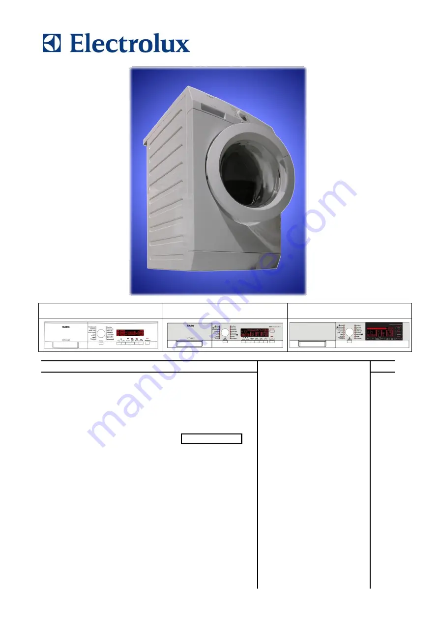
background image

SERVICE MANUAL


WASHING


Washing machines 


with electronic control 

system 


EWX11831 
EWX14931 

UIMC / EMC14 

Inverter  


Technical and functional 

characteristics 


NEW 

COLLECTION


SERIES 


7/8/9


 ELECTROLUX HOME PRODUCTS 

Customer Care - EMEA 
Training and Operations Support 
Technical Support 
 

Publication 

number 


599 77 23-65


Edition: 06/2015 - Rev. 03 


EN 


SERIES 7 

SERIES 8 

SERIES 9 


Содержание EWX11831

Страница 1: ...31 EWX14931 UIMC EMC14 Inverter Technical and functional characteristics NEW COLLECTION SERIES 7 8 9 ELECTROLUX HOME PRODUCTS Customer Care EMEA Training and Operations Support Technical Support Publication number 599 77 23 65 Edition 06 2015 Rev 03 EN SERIES 7 SERIES 8 SERIES 9 ...

Страница 2: ...Technical Support DMM 2 106 599 77 23 65 Rev 03 ...

Страница 3: ...ay 26 5 2 1 3 Programme selector S1 26 5 2 1 4 Programme configuration 26 5 2 1 5 Pushbuttons LEDs and LCD 27 5 2 1 6 Buzzer 31 5 2 1 7 Weight sensor where featured 31 5 2 1 7 1 Enabling Disabling the weight sensor 31 6 DEMO MODE 32 6 1 Access to DEMO settings 32 6 2 Exiting DEMO mode 32 7 DIAGNOSTICS SYSTEM 33 7 1 Accessing diagnostics 33 7 2 Quitting the diagnostics system 33 7 3 Phases of the d...

Страница 4: ...nent magnets 60 13 10 1 General characteristics Power supply to motor 60 13 10 2 Operating principle 61 13 11 Inverter UIMC EMC14 62 13 11 1 General characteristics 62 13 12 Circulation pump where featured 63 13 12 1 General characteristics 63 13 13 Solenoid valves 63 13 13 1 General characteristics 63 13 13 1 1 Operating principle 64 13 13 1 2 Mechanical jamming of the solenoid valve 64 13 13 1 3...

Страница 5: ...97 16 4 5 Pressure chamber 97 16 4 6 Tub suspension springs 99 16 4 7 Shock absorber pin 100 16 5 Accessing the rear part 101 16 5 1 Back panel 101 16 6 From the back panel you can access 101 16 6 1 Belt 101 16 6 2 Plastic pulley 102 16 6 3 Inverter 102 16 6 4 Motor 103 16 6 5 Heating 103 16 6 6 Water control 103 16 6 7 Shock absorbers 104 16 6 8 Welded tub assembly 104 16 6 9 Drain pipe cabling s...

Страница 6: ...or after the end of the cycle the appliance receives no further instructions it is automatically turned off for energy savings in conformity with the standards on energy consumption All the settings are stored so that when the appliance is turned back on the programme is ready or if the auto off mode was triggered after the end of the cycle the user can see that the cycle ended normally and can re...

Страница 7: ...trolux Learning Gateway portal This platform is not fitted with an ON OFF switch Before you access internal components take the plug out of the socket to cut the power supply Make resistance measurements rather than direct voltage and current measurements Warning the sensors located on the display board could be at a potential of 220 Volts When replacing the heating element replace it with one tha...

Страница 8: ...ated in the circuit board Serial port DAAS EAP communication protocol up to 115 200 baud Power supply voltage 220 240 V 50 60 Hz configurable Washing type Traditional with Eco ball sphere Jet System Rinsing system Traditional with Eco ball sphere Jet System Motor Two pole asynchronous three phase Three phase synchronous Spin speed 400 1 600 rpm Anti unbalancing system AGS Cold water fill 1 solenoi...

Страница 9: ... 16 position programme selector 20 LEDs LCD Initial production LCD version Current production LCD version Positioning of LEDs and buttons Display board assembly exploded view 1 Selector board protection 2 Display board protection 3 LCD screen 4 Display board and selector board 5 Rear protection ...

Страница 10: ...hing cycles e g water level drum movement no of rinses and the washing temperature to be selected according to the type of garments The selector can be turned both clockwise and anti clockwise For each programme the compatible options and other parameters are defined 3 2 2 2 Programme configuration The table below lists the parameters that can be used to define the washing programmes Types of fabr...

Страница 11: ...play is the one set for the programme selected Press this button in sequence to lower the temperature when the lowest temperature is reached the selection will start again from the highest one available for the programme The temperatures available displayed in C are 95 C 60 C 50 C 40 C 30 C 20 C cold cycle The cold cycle is displayed by two dashes Button no 3 SPIN SPEED This is related to the part...

Страница 12: ... twice for the Super Quick function the relevant LED will remain on fixed and at the same time the three digit display will vary the cycle time Stains and HOT and COLD Water are alternative options for the same button When the hot water solenoid is present the relevant option is also configured Button no 7 DELAYED START This button is configurable and has the DELAYED START function During the prog...

Страница 13: ...tion a key combination needs to be pressed It may be silk screen printed on the control panel or described in the instruction manual Door closed sensor Lights up when the safety device stops door opening and switches off when the door can be opened Flashes when the device is about to unlock the door Washing programme time This appears after a washing programme has been selected This time correspon...

Страница 14: ... flashes Calculate amount of washing Only for appliances with PROPORTIONAL programmes After starting the washing programme the dot starts to flash At this point the washing machine calculates the amount of washing inside the drum When this phase ends the dot lights up fixed and the three digits display the programme time Extra rinse Appliances which do not feature the button and related LED for th...

Страница 15: ...tted with the buzzer and leave the factory with the option enabled To disable it use the combination of keys The volume level is set in the factory and cannot be adjusted by the user When the buzzer is disabled using the combination of keys it only emits the short Click and the sequence of three short beeps when an alarm is triggered During the programme selection phase the buzzer can be enabled d...

Страница 16: ...gramme selector 16 positions incorporated in the circuit board Serial port DAAS EAP communications protocol up to 115 200 baud Power supply voltage 220 240 V 50 60 Hz configurable Washing type Traditional with Eco ball sphere Jet System Rinsing system Traditional with Eco ball sphere Jet System Motor Two pole asynchronous three phase Three phase synchronous Spin speed 400 1 600 rpm Anti unbalancin...

Страница 17: ...2 1 Styling Max 9 10 buttons 16 position programme selector 20 LEDs LCD Positioning of LEDs and buttons Display board assembly exploded view 1 Selector board protection 2 Display board protection 3 LCD screen 4 Display board and selector board 5 Rear protection 1 2 3 4 5 ...

Страница 18: ...grammes the functions of the selector knob and the various buttons vary according to the model since these are determined by the configuration of the appliance 4 2 1 2 Programme selector S1 Description see para 3 2 2 1 on page 10 4 2 1 3 Programme configuration Description see para 3 2 2 2 on page 10 ...

Страница 19: ...ycle When no speed is selected or the Rinse Hold cycle is selected the LCD display shows three dashes The settings described below not only have symbols but they are also accompanied by a graphic bar within a frame If it is illuminated this indicates that the option is enabled for the chosen programme otherwise it is off When all its segments are lit it will start from scratch again the next time ...

Страница 20: ...ry time the button is pressed The symbol lights and stays on for the entire delay phase During the programme selection phase a delayed start can be selected from 30 to 20 hours 30 60 90 2h 3h 20h 0h and the time is shown on the display during the final hour the time shown decreases minute by minute During the last hour the time decreases minute by minute To cancel the delayed start time after the ...

Страница 21: ...which needs one two minutes to open Weight sensor Group of icons representing the weight information of the laundry inside the drum Since they represent the maximum load possible the actual weight of the laundry inside the drum and the ratio of these two factors suggests the quantity of detergent to pour into the detergent dispenser Description see para 5 2 1 7 on page 31 Washing programme time De...

Страница 22: ...he Extra rinse option can enable disable this option by pressing a key combination which may be silk screen printed on the control panel or described in the instruction manual This option is enabled disabled during programme selection and is confirmed by the related symbol being turned on off The option remains enabled even after the appliance has been turned off for subsequent programmes 4 2 1 5 ...

Страница 23: ...w the maximum weight without warning that the load is excessive Whereas in other programmes Synthetics delicates special programmes and in particular the drying programmes if the weight exceeds by only 1 kg or more the symbol MAX will begin to flash together with the weight of the maximum load allowed In some cases you will have to take some laundry out so that the symbol MAX and the maximum weigh...

Страница 24: ...with the motor control board Inverter and with the weight sensor where featured No buttons Max 1 ON OFF No of sensors Max 10 options start pause memories No LEDs Maximum 22 LCD Programme selector 16 positions incorporated in the circuit board Serial port DAAS EAP communications protocol up to 115 200 baud Power supply voltage 220 240 V 50 60 Hz configurable Washing type Traditional with Eco ball s...

Страница 25: ... Max buttons 1 Max sensors 10 16 position programme selector 22 LEDs LCD Positioning of LEDs and buttons Display board assembly exploded view 1 Selector board protection 2 Seal 3 Display board protection 4 LCD screen 5 Display board and selector board 6 Rear protection 1 2 3 4 5 6 ...

Страница 26: ... After the language has been selected the text line shows Time of day prompting you to set the time After approximately 3 seconds you will be prompted to turn the selector which will change the time by an hour in the digits every time it is moved Once the correct time has been set confirm by pressing the START PAUSE sensor The digits relating to the minutes start to flash Again turn the selector d...

Страница 27: ...e temperatures available displayed in C are 95 C 60 C 50 C 40 C 30 C 20 C cold cycle Concurrently with the display of the temperature in degrees the name of the selected function appears at the top of the display in the text line Sensor no 2 SPIN SPEED It is related to the part of the LCD display see figure where the spin speed of the washing cycle is shown The initial speed shown on the LCD displ...

Страница 28: ...s to light up Concurrently the symbol lights up and you can choose the number of rinses to add to the programme which are displayed by the digit depending on the programme Concurrently to the displaying of the symbol for the option as the graphic bar is gradually illuminated the name of the option is displayed in the text line in the top left Sensor no 5 OPTION It is related to the part of the LCD...

Страница 29: ...ts up and the words Programme saved are displayed in the text line to show that the operation was successful To recall the stored programme simply touch the sensor s8 9 of the memory concerned the corresponding LED L2 3 lights up and the LCD displays the settings of the programme saved selector LED options time left and the words Memory programme are displayed in the text line for approximately 3 ...

Страница 30: ...inside the drum Since they represent the maximum load possible the actual weight of the laundry inside the drum and suggests the quantity of detergent to pour into the detergent dispenser Description see para 5 2 1 7 on page 31 Delayed start Selected on the related sensor After the START PAUSE button is pressed the countdown starts and the delay time decreases hour by hour from a delay of 20 hours...

Страница 31: ...aduated bar Concurrently to the loading of the laundry in the drum the LCD display is updated for both the weight and time left until the end of the cycle In the event of an overload in a programme Cottons the LCD display will continue to show the maximum weight without warning that the load is excessive Whereas in other programmes Synthetics delicates and special programmes if the weight exceeds ...

Страница 32: ... the drain pump are disabled Display as the cycle phases are very fast one second in the demo cycle corresponds to approximately one minute in the actual cycle the end time decreases by 1 unit per second Bear in mind that the end time does not always correspond to the actual cycle time 6 1 Access to DEMO settings The operations listed below must be carried out within 7 seconds SERIES 7 SERIES 8 SE...

Страница 33: ...ence approximately 3 seconds In the first position the operation of the buttons of the related LEDs and of the groups of symbols shown on the LCD screen is checked turn the programme selector dial clockwise to run the diagnostic cycle for the operation of the various components and to read any alarms see diagnostic testing on the following page During this phase if any key combination is pressed e...

Страница 34: ...ter level below anti flooding level Maximum time 5 mins Water fill to pre wash compartment Water level in the tub mm 4 Door safety interlock Solenoid valve pre wash and wash Door closed Water level below anti flooding level Maximum time 5 mins Water fill to conditioner compartment Water level in the tub mm 5 Door safety interlock Third Solenoid valve Door closed Water level below anti flooding lev...

Страница 35: ...acklighting comes on When a button sensor is pressed the group of icons on the LCD display or the corresponding LED lights up and the buzzer sounds Always active User interface functions In most cases this time is sufficient to check the heating However the time can be increased by repeating the phase without draining the water pass for a moment to a different phase of the diagnostic cycle and the...

Страница 36: ... exception of alarms associated with the configuration and the power supply voltage frequency which are also displayed during the programme selection phase The door can normally be opened except where specified when an alarm condition has occurred on the condition that The water in the tub is below a certain level The water temperature is lower than 55 C The motor has stopped Certain alarm conditi...

Страница 37: ...continues to perform the cycle or if you in the selection phase any options that have already been selected will remain in the memory 8 4 Deleting the last alarm It is good practice to cancel the alarms stored After reading the alarm codes to check whether the alarm re occurs during the diagnostic cycle After repairing the appliance to check whether or not it occurs again during testing Series 7 S...

Страница 38: ...a clockwise direction until the fifth LED in the right hand row lights up 3 Press the START PAUSE button and the nearest option button simultaneously as shown in the figure 4 Hold down the buttons until the hours of operation appear on the display at least 5 seconds 9 2 Display of total operating time This time is displayed with a sequence of two digits at a time the first two digits indicate thou...

Страница 39: ...mum steam Compatibility with OPTIONS Rinse hold X X X X X X X X X X X X X Night cycle X X X X X X X X X X X Pre wash Soak X X X X X X X X X X X X X X X X Stains X X X X X X X X X X X X X X X X Super rinse X X X X X X X X X X X X X X X Easy iron X X X X X X X X X X X X X X Economy X X X X X X X X X X X X X Cupboard Dry X X X X X X X X X X X X X Daily X X X X X X X X X X X X X Super Quick X X X X X ...

Страница 40: ...for WOOL and HAND WASH cycles Super rinse SERIES 7 Adds two rinses in the COTTONS SYNTHETICS DELICATES cycles Eliminates the spin at the end of washing Super rinse SERIES 8 9 key combination Adds two rinses in the COTTONS SYNTHETICS DELICATES cycles Eliminates the spin at the end of washing EXTRA rinse SERIES 8 9 Adds up to five rinses in the COTTONS SYNTHETICS DELICATES cycles When the rinses are...

Страница 41: ...by pressing the relevant button then press Start Pause again 11 Generating STEAM In SERIES 8 and 9 certain programmes can be configured to generate steam which is used to refresh the laundry or to remove some creases and make ironing easier To obtain steam during theses programmes the quantity of water filled in the tub must be enough to cover the heating element and the maximum temperature to rea...

Страница 42: ...tion pump 6 Drainage pump 7 Shock absorbers 8 Water control 9 Detergent dispenser 10 Washing unit suspension springs 11 Front counterweight 12 Solenoid valves 13 Washing unit 14 Upper counterweight 15 Motor 16 Heating 17 Belt 18 Inverter motor control board 19 Analogue pressure switch 20 Back unit casing 21 Main electronic circuit board 22 Crossbar 23 Worktop 24 Back panel ...

Страница 43: ... wash phase Water fill to wash compartment wash solenoid In all models compartment b is used to contain the detergent loaded at the start of the washing Water fill to activating wash compartment In models with 4 compartment dispenser trays the filling in tray d is performed by a purpose provided solenoid valve during washing when the water has reached 40 C In models with 3 compartment dispenser tr...

Страница 44: ...been fitted inside compartment b where the detergent is introduced which can be flipped up or down With the flap flipped up the appliance is ready for use with powder detergent this is the factory setting see figure opposite To modify the position of the flap pull the detergent dispenser out see page 90 With the flap flipped down the appliance is ready for use with liquid detergent For further det...

Страница 45: ... spin phases the counterweights are secured in place with screws one at the front 3 and one at the top 7 The bellow seal 4 is fixed at the front The washing unit is suspended by two coil springs 8 attached to the top crossbar and the oscillations are dampened by three shock absorbers two on the right 9 and one on the left 10 looking straight at the front of the appliance In washing machines in the...

Страница 46: ...n circuit 1 Filter body tub tube 2 Pressure chamber 3 Drain pipe 4 Drainage pump 5 Filter body 6 Filter or needle trap 7 Filter body seal 8 Filter knob seal 9 Filter dial 10 Locking lever seal 11 Locking lever 12 Circulation pump suction tube 13 Re circulation pump 12 5 3 JET circuit The water circulating through the drain circuit 1 during the washing is suctioned along the tube 2 by the circulati...

Страница 47: ...ctronic control 12 6 1 Programming Updating the main circuit board Any programming updating diagnostics operation carried out with the board installed on the appliance and the mains plug disconnected from the socket If one of these operations is accidentally carried out when plugged in to the socket on completing the operation the appliance will remain turned off when restarting disconnect the plu...

Страница 48: ...ectrical components cold and hot water solenoid valve where featured motor control board Inverter drain pump circulation pump where featured heating element door safety interlock drum light It controls the level of water via the analogue pressure switch It controls the state of the door It controls the speed of the motor It controls the temperature of the wash water via the NTC probe inserted in t...

Страница 49: ...Technical Support DMM 49 106 599 77 23 65 Rev 03 ...

Страница 50: ...he emission of radio frequency disturbances in the power network It is incorporated into the main board 1 Main electronic circuit board 13 2 Display board The main circuit board 1 supplies the power supply voltage to the control display board 12 It is possible to select the programmes by turning the selector The options can be selected by pressing touching the buttons keys and the START PAUSE butt...

Страница 51: ...e foreign body is released The flow rate of these pumps is approximately 18 20 l min and the maximum head is 90 cm above ground level Fitted with overload cut out Important Synchronous pumps when powered on empty disconnected from the water circuit may not start in some cases because their very construction makes them need an antagonist torque on the wheel to allow the rotor to move in one of the ...

Страница 52: ...rned off with the plug inserted into the power socket In the bottom of the washing machine there is a plastic bottom that forms a container This collects any water leakage from the tub from the pipes etc which flows into the area in which the float is positioned made of polystyrene In the presence of water this lifts up and triggers the microswitch which powers the drain pump When it is triggered ...

Страница 53: ...1 General characteristics 1 NTC probe 2 Heating element The heating element of the washing water is armoured i e it is inserted in sealed tubular stainless steel casing It is powered by two relays K1 K2 situated in the circuit board It is fitted with two thermal fuses which trip if the temperature of the heating element exceeds the values for which they were calibrated In the event of a fault an a...

Страница 54: ...stic casing An NTC type probe is used to control the washing temperature it is built in such a way that its internal resistance decreases as the temperature rises This drop in resistance is detected by the electronic control which when the desired temperature is reached disconnects the heating element The temperature of the water is controlled by the circuit board by means of an NTC temperature pr...

Страница 55: ...e pressure chamber When water is introduced into the tub this creates a pressure inside the hydraulic circuit that causes the membrane to change position This in turn modifies the position of the core inside the coil thus changing the inductance and the frequency of the oscillating circuit The PCB recognises how much water has been introduced into the tub according to the frequency 1 Main electron...

Страница 56: ...Support DMM 56 106 599 77 23 65 Rev 03 13 8 Shock absorber with weight sensor where featured 13 8 1 General characteristics 1 Plunger 2 Weight sensor 3 Piston 1 Main electronic circuit board 6 Weight sensor 1 2 3 ...

Страница 57: ...undry in the drum when the appliance is turned on the position of the piston is different from when the drum is empty moving the zero value and offsetting the final measurement Efficacy check To check the efficacy of the weight sensor Check that the inside of the drum is empty Plug the appliance into the socket press button P1 to turn it on and select the desired programme Open the appliance door ...

Страница 58: ...d 3 Lifting assembly 4 Cam Labyrinth 5 Locking pin 6 Electrical contacts main switch 7 Door sensing switch 8 Cursor When the programme starts start pause button the main circuit board sends a voltage pulse lasting 20 msec to the valve 2 at least 6 seconds should have passed since turning it on which moves the cam 4 to a locking position the blocking pin 5 is pushed locking the cursor 8 and simulta...

Страница 59: ...lure or the appliance being turned off with the ON OFF button before the wash cycle ended or valve malfunction or faulty main board because inside they had a PTC bi metal which allowed the door to be opened after cooling between 55 seconds and 4 minutes The new device has a manual opening system which allows the door to be opened following the instructions below Before activating the manual openin...

Страница 60: ...nected The phase shift between the phases is 120 and peak amplitude is 310V It is possible to get an idea of the continuity of the motor winding by measuring the resistance of the coils value at 25ºC Coil y ohm 5 35 7 contacts 2 3 Coil x ohm 5 35 7 contacts 1 2 Coil z ohm 5 35 7 contacts 1 3 Medium Performance MOTOR PM Coil y z ohm 6 56 7 contacts 2 3 Coil x y ohm 6 56 7 contacts 1 2 Coil z x ohm ...

Страница 61: ...s three phase alternating current the magnetic field of the stator has a fixed intensity and variable direction rotating hence a rotating magnetic field is produced The speed of rotation of the rotating magnetic field is proportional to the frequency and inversely proportional to the number of poles The magnetic field of the rotor is generated by the permanent magnets which are positioned in the r...

Страница 62: ...he combination of the opening and closing of switches I1 I6 piloted by the µprocessor determines the piloting voltage and frequency of the motor Clockwise rotation of the motor Anti clockwise rotation of the motor The motors powered by this inverter do not have tachometric winding The inverter can detect adjust the motor speed via the current absorption During the spin phases the microprocessor ca...

Страница 63: ...tor 1 Main electronic circuit board 2 Door safety interlock with Door sensing switch 2a Door safety interlock without Door sensing switch 15 Re circulation pump Important Synchronous pumps when powered on empty disconnected from the water circuit may not start in some cases because their very construction makes them need an antagonist torque on the wheel to allow the rotor to move in one of the tw...

Страница 64: ...d valve may jam open without being actuated which will cause flooding if the pressure switch controlling the water level does not trip If this occurs the electronic control system which continuously monitors the flow sensor will lock the door start the drain pump and display an ALARM simultaneously 13 13 1 3 Low water pressure If the flow sensor does not generate a signal during the water fill pha...

Страница 65: ... of solenoid valves have a built in flow sensor which measures the quantity of water in litres that is loaded into the appliance In the event of a sensor failure the water level is controlled by the analogue pressure switch Electronically controlled valve exploded view PCB Turbine 1 PCB 4 Diffuser 2 Turbine 5 Double filter 3 Deflector 6 Reed contact 7 Magnet Flowmeter ...

Страница 66: ...rotates the turbine 1 and magnet 3 which passes in front of the Reed contact 2 thus closing it As this contact opens and closes it generates pulses at a frequency that depends on the water flow rate The turbine completes 230 revolutions for each litre of water The operating range of the flow sensor is 0 2 10 bar Using the signal it receives the micro processor can calculate the number of litres of...

Страница 67: ... the LED lights up and illuminates the inside of the drum Vice versa when the door is closed the LED is turned off IMPORTANT Do not look straight at the light beam emitted by the LED when it is on To check the efficiency of the LED power it with constant direct current of 150 mA and a voltage of 3 3 V For the power supply please refer to the polarities in the figure opposite 1 Main electronic circ...

Страница 68: ... Air trap system leaking Air trap systems clogged Pressure switch defective Cycle Paused with door locked START RESET E21 Difficulties in draining for washing Water drain timeout expired measured for each drain phase of a washing cycle Drain pipe blocked up Blocked dirty filter Drain pump defective Pressure switch defective Wiring or main Board defective Drain pump rotor locked Cycle Paused after ...

Страница 69: ...Cycle Paused START RESET E42 Door lock device failure Door still locked when opening timeout of 4 minutes Door lock device defective Wiring or main board defective Current leakage between heater element and earth Cycle Paused START RESET E43 Door lock device triac failure Incongruence between door lock device triac sensing and triac status Door lock device defective Wiring or main board defective ...

Страница 70: ...ctive Washing heater element defective Wiring or main board defective Heating phases skipped START RESET E62 Overheating during washing cycle Water temperature higher than 88 C for a time longer than 5 minutes Washing NTC defective Wash heater element defective Wiring or main board defective Safety Drain cycle Cycle stopped with door unlocked RESET E66 Heater or drying relay failure Incongruence b...

Страница 71: ...on UI microprocessor User interface defective START ON OFF RESET E87 User Interface microcontroller fault User interface microcontroller damaged User interface defective No actions to be performed If still present replace the User Interface Board START ON OFF RESET E91 UI MB communication error Communication problem between UI and MB Wiring defective or UI MB Motor WD Weight board defective RESET ...

Страница 72: ...ON EBD EHD Heater WD relay sensing alarm Wrong input signal to microprocessor Main board defective Cycle blocked with door locked RESET EBE EHE FCV Relay failure Incongruence between safeties relay sensing and FCV relay status FCV Relay defective FCV sensing circuit defective Wiring or main board defective Safety Drain cycle activation stop of the cycle with door opened RESET EC1 Electro valves bl...

Страница 73: ...ermostats defective Main Board defective Skip drying phase START ON OFF RESET ED3 WD heating element1 sensing relay failure Signal out of the limits WD board defective Skip drying phase START ON OFF RESET ED4 WD heating element2 relay failure Incongruence between WD heating2 relay sensing and heating1 relay status WD board defective wiring thermostats defective Main Board defective Skip drying pha...

Страница 74: ...ART ON OFF RESET EF1 Filter clogged warning Difficulties to drain Virtual AB level remains in full state after an established time Filter clogged or dirty Drain pipe clogged kinked too high Warning displayed at the end of the cycle START RESET EF2 Foam warning Virtual AB level in full state during spin phase at the end of the washing phase Excessive detergent dosing Drain filter dirty or clogged D...

Страница 75: ...Technical Support DMM 75 106 599 77 23 65 Rev 03 15 DIAGRAMS 15 1 EWX11831 Diagram with THREE PHASE ASYNCHRONOUS MOTOR ...

Страница 76: ...lenoid valve 9 Bleach solenoid valve 10 Hot water solenoid valve 11 Heating element 12 Display board 13 Motor control board Inverter 14 Triple phase motor 15 Re circulation pump 16 Aqua control sensor 17 Drainage pump 18 Drum light DRAIN_YTY Drain pump TRIAC DOOR_TY Door interlock TRIAC DOOR_CLOSE_TY Door interlock TRIAC REC PUMP_TY Circulation pump TRIAC switch PWELT_TY Pre wash solenoid TRIAC WE...

Страница 77: ...Technical Support DMM 77 106 599 77 23 65 Rev 03 15 2 EWX14931 Diagram with THREE PHASE ASYNCHRONOUS MOTOR ...

Страница 78: ...play board light diffuser buttons buttons springs assembly 5 Electronic pressure switch 6 Detergent dispenser 7 Detergent fill pipe 8 Upper counterweight 16 2 1 EWX11831 Main board Remove the worktop see relevant paragraph Pull out the power supply cable from the hooks and from the connector Unfasten the three screws securing it to the cabinet Pull out the wiring of the hooks positioned at the rea...

Страница 79: ...ve the main board Release the hooks securing the connectors protection on one side then the other Remove the connectors protection Pull out the connectors positioned beside the board Pull out the other connectors taking care as they are retained by hooks ...

Страница 80: ...to the board Slide off the connector Unfasten the two screws securing it to the cabinet Remove the clamp that secures the wiring to the spring support bracket Using a pair of pliers remove the clamps that secure the wiring to the power board assembly container indicated by the arrows Position the board assembly as shown in the figure Remove the connectors and the faston that connects the earth bew...

Страница 81: ...mber to use the anti sliding kit Unhook the three hooks that join the two casings on one side and on the other Lift the lid Release the three hooks that secure the board to the container and remove it take care not to break the hooks Remove the connectors ...

Страница 82: ...iring is inside the box So that when the lid is closed the wiring is not crushed or cut by the two plastic parts Fit the connectors into their proper slots and arrange the wiring as shown in the figure Before securing the side clamp Restore the earth connection fit the power supply connector and insert it between the two hooks ...

Страница 83: ...er fill pipe from the solenoid valve Push the two retainers indicated by the arrows towards the inside of the appliance At the same time turn the solenoid valve to remove it 16 2 4 Control panel Remove the worktop see relevant paragraph Pull the detergent dispenser out and at the same time press the stop locking it in place Loosen the screws that attach the control panel to the detergent tray Pull...

Страница 84: ...l so as to pull out the hooks which secure it to the front panel Remove the control panel and position it as shown in the figure making sure you introduce a protection to prevent scratching it 16 2 5 Display board light diffuser button springs buttons assembly Remove the worktop see relevant paragraph Remove the control panel see relevant paragraph Remove the screws and release the hooks which sec...

Страница 85: ...ol panel Buttons The buttons have a number printed on them See the figure for numbers Selector light diffuser To remove unhook the hooks that fasten it to the control panel when reassembling the display board assembly and the control panel Remove the dial from the dial cover Release the hooks that fasten them together and fasten the whole to the control panel Illustration of the dial and the dial ...

Страница 86: ...he dial onto the selector pin Insert the display board in its seat in the control panel Insert the dial cover SERIES 8 and 9 if the two earth wires connecting the front panel have been disconnected reconnect them to the fastons of the control panel crosspiece ...

Страница 87: ...t 16 2 7 Detergent dispenser Remove the worktop see relevant paragraph Remove the control panel see relevant paragraph Pull out the pipes that connect it to the solenoid valves cold water and where featured hot water Unfasten the two screws securing it to the central crosspiece Unfasten the screw in the clamp that fixes the detergent loading pipe to the tray and remove it from its housing If the a...

Страница 88: ...spenser make sure the two references are aligned 16 2 9 Upper counterweight Remove the worktop see relevant paragraph Remove the three screws that secure it to the welded tub When reassembling If the tub assembly is new tighten the screws at a torque of 20 Nm If the tub assembly is not new align with the existing thread and tighten the screws at a torque of 15 Nm 16 3 Accessing the front part From...

Страница 89: ...screws securing the door safety interlock to the front panel Take the device and move it to the left Turn it towards the inside right hand side of the flange Pull it out towards the right and remove it Pull out the door safety interlock Take care in the lower part of the device as there is a small rod Don t pull it out too much otherwise the small rod comes out of its seat in the filter body as de...

Страница 90: ...f the page Make sure the small rod to release the door safety interlock is correctly positioned and visible in its seat by opening the filter flap To reassemble the door safety interlock repeat the same tasks in reverse order Before tightening the screws to secure the door safety interlock to the front panel make sure the flange is positioned properly on the outside as indicated by the arrows Tigh...

Страница 91: ...seat in the bellow seal after breaking the clamp when reassembling use a new clamp with the same characteristics and size 20 5 Take the seal out of the welded tub take care as the seal is held in position by a snap ring When reassembling the seal lubricate with liquid soap the part where the tub is inserted Make sure the references are aligned Reassemble the snap ring between the door bellow seal ...

Страница 92: ... drum Insert a flat tip screwdriver into hole 6 see figure Place the screwdriver with the handle tilted towards the right Push the left hand tab downwards Place the screwdriver with the handle tilted towards the left Push the right hand tab down When the two tabs are down move the blade towards the front of the drum and if necessary squash the blade at the two ends 1 6 1 6 ...

Страница 93: ... guides Push it towards the back Insert the flathead screwdriver at a right angle to the blade hole 6 so as to position it at the centre of the two tub tabs Tilt it towards the right so that the left tab moves upwards With the screwdriver still inserted in the slot tilt it towards the left so that the right tab moves upwards With the tabs raised the blade is secured to the drum ...

Страница 94: ... two screws that secure the plinth to the front Release the two hooks that secure it to the front indicated by the arrows Remove the plinth by turning it downwards in order to pull out the pins that secure it to the lower part of the front panel Loosen the screws that secure the lower part of the front panel to the cabinet casing Release the cable clamp secured to the centre of the front panel whe...

Страница 95: ...irculation pump while you will have to break widen the clamp from the bellow seal when reassembling use a new clamp with the same characteristics with size 20 5 Re circulation pump Remove the protection 2 Disconnect the connectors 3 Move the lock catch 4 with some pliers take care not to break it Turn the pump in the direction shown by the arrow 5 Remove the pump To remove the circulation pump scr...

Страница 96: ...ut the lamp from its seat Unfasten the five screws securing the front counterweight to the welded tub assembly When tightening the screws take care If the welded tub assembly is new tighten the screws at a torque of 15 Nm If the welded tub assembly is not new align with the existing thread and tighten the screws at a torque of 10 12 Nm 16 4 3 Shock absorber with without weight sensor Remove the wo...

Страница 97: ...rain pipe and pull out the pressure chamber 3 Where clamps are present you will need to open break them When reassembling use clamps with the same characteristics 16 4 5 Pressure chamber Remove the worktop see relevant paragraph Remove the control panel see relevant paragraph Remove the iron ring securing the bellow seal to the front panel Unfasten the screws securing the door safety interlock see...

Страница 98: ...e cabinet Filter body Remove the worktop see relevant paragraph Remove the control panel see relevant paragraph Remove the iron ring securing the bellow seal to the front panel Unfasten the screws securing the door safety interlock see related paragraph Remove the front panel see relevant paragraph Loosen the screws securing it to the front crossbar 1 Pull out the main drain pipes 2 and circulatio...

Страница 99: ... the right spring When reattaching the springs after repair work which required their removal make sure that the bushings shown in the figure are featured on both ends Pay attention to the differences between the bushings see enlarged details Spare bushings are available under the following codes Upper bushing Code 405 50 62 51 9 Lower bushing Code 405 50 62 52 7 Apply some grease on either end of...

Страница 100: ...in is inserted see the two figures below When positioning the shock absorber inside the fastening situated at the bottom of the cabinet or in the tub take care when positioning the bushing so as to insert the pin from the part of the bushing with the widest profile The spare bushing is supplied under Code 344 91 25 30 5 If you are having difficulty inserting the pin grease it a little code 5026 24...

Страница 101: ...embly 9 Drain pipe cabling support 10 Main drain pipe 16 6 1 Belt Remove the back panel see relevant chapter Hold the belt and by turning the pulley remove it When reassembling Position the belt and align it with the centre of the pulley 273 mm as shown in the figure Turning the pulley check that the belt positions itself and remains in the central part of the pulley If necessary adjust the positi...

Страница 102: ...t Tighten the screw at a torque of 60 Nm 16 6 3 Inverter Remove the back panel see relevant chapter Loosen the two screws that fix it to the cabinet Pull out the clamp from the cabinet Push the washing unit towards the inside of the appliance if necessary Pull out the connectors of the heating element if necessary Remove the Inverter UIMC Disconnect the hooks fixing the connector protection on one...

Страница 103: ...power supply and earthing blue arrow and also slip off the strap Loosen the two front fastening screws 1 and the rear ones 2 red arrows When reassembling restore the connections If the clamp securing the wiring to the motor breaks replace it with a new one Tighten the screws at a torque of 5 Nm 16 6 5 Heating Remove the back panel see relevant chapter Disconnect the connectors of the heating eleme...

Страница 104: ...raph To remove the washing unit assembly disconnect All the tub pipes the wiring connectors that connect the heating element the NTC probe remove the belt and the motor to lighten the tub Lay the appliance on its back making sure you place a polystyrene or cardboard layer on the floor to prevent damaging the cabinet Take the tub out of the washing machine 16 6 9 Drain pipe cabling support When fix...

Страница 105: ...5 106 599 77 23 65 Rev 03 16 6 11 Main drain pipe Arrange the drain pipe as shown in the figures 16 6 12 Power supply cable clamp Squeeze it using a pair of pliers while at the same time pulling it out into the cabinet 1 2 3 4 ...

Страница 106: ...rom EWM10 to EWX11 Pag 60 the text was modified between attention box and the box where there are graphics Pag 63 Corrected the description of the reference 9 DMM XX 0X 201X 02 03 2015 Updates for EWX14931 Alarm Table Summary Diagram EWX14931 Main board Accessibility MP XX 0X 201X 02 06 2015 Updates for Medium Performance MOTOR PM MP XX 0X 201X ...

Отзывы: