background image

Technical Support - MDM


71/97 

599 76 11-68 Rev. 01


14  ACCESSIBILITY 


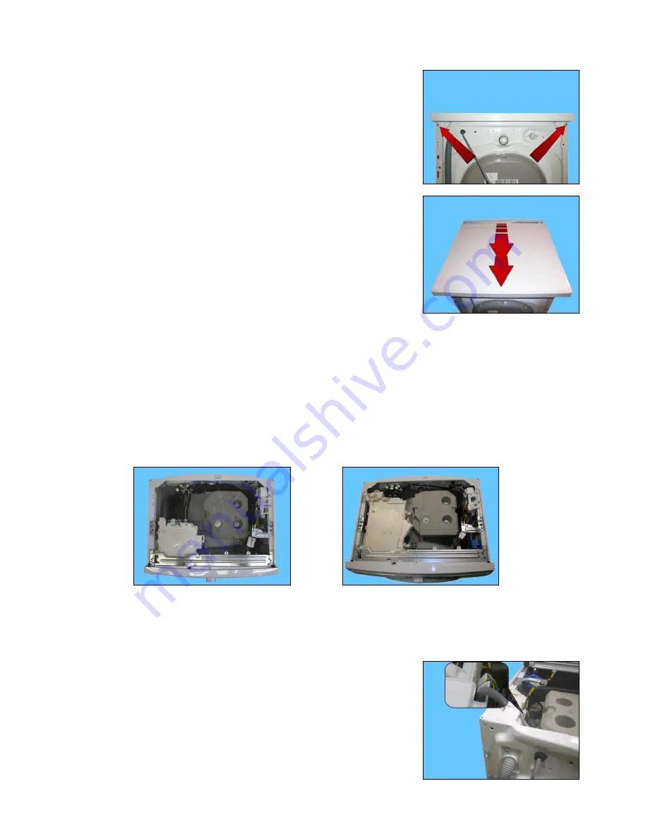
14.1  Worktop 


Remove the screws that secure it to the back panel. 


Pull it out from the back. 


14.2  From the worktop, you can access 

 
1.  Main board 
2.  Solenoid valves 
3.  Control panel 
4.  Assembly of display board/selector/LEDs light diffuser 
5.  Electronic pressure switch 
6.  Short/Long detergent dispenser 
7.  Detergent fill pipe 
8.  Top counterweight 


Short dispenser 

Long dispenser 


14.2.1  Main board EWM09312 


Remove the worktop (see relevant paragraph). 
Take the power supply cable out of the hook that secures it  
to the main PCB casing. 


Содержание EWF1284EDW

Страница 1: ...Service Catalog PNC ELC Brand Category Model EWF1284EDW 914533914 01 Electrolux Washer FL EWF1284EDW ...

Страница 2: ...Technical Support MDM 2 97 599 76 11 68 Rev 01 ...

Страница 3: ... DEMO setting for TC3 styling 27 5 2 Accessing the DEMO setting for TC4 styling 27 5 3 Exiting DEMO mode 27 6 DIAGNOSTIC SYSTEM 28 6 1 Accessing diagnostics for TC3 styling 28 6 2 Accessing diagnostics for TC4 styling 28 6 3 Quitting the diagnostics system 28 6 4 Phases of the diagnostics test 29 7 ALARMS 32 7 1 Displaying user alarms 32 7 2 Reading the alarms 33 7 3 Rapid reading of arms 33 7 4 D...

Страница 4: ...lowmeter 61 12 ALARM SUMMARY TABLE 62 13 DIAGRAMS 67 13 1 EWM09312 Operating Circuit Diagram 67 13 2 EWM09312 Operating circuit diagram key 68 13 3 EWX13611 Operating Circuit Diagram 69 13 4 EWX13611 Operating circuit diagram key 70 14 ACCESSIBILITY 71 14 1 Worktop 71 14 2 From the worktop you can access 71 14 2 1 Main board EWM09312 71 14 2 2 Main board EWX13611 73 14 2 3 Solenoid valve 76 14 2 4...

Страница 5: ...M 5 97 599 76 11 68 Rev 01 14 7 2 Plastic pulley 273 mm 94 14 7 3 Motor 94 14 7 4 Resistance 94 14 7 5 Drain pipe wiring support 95 14 7 6 Drain pipe fastener 95 14 7 7 Main drain pipe 95 14 7 8 Power supply cable clamp 96 ...

Страница 6: ...sumption mode In order to reduce electricity waste when the cycle is not running the appliances on this platform are designed to enter consumption reduction mode 1 1 1 TC4 TC3 with universal motor EWM09312 EWX13611 Stand Off mode When the appliance is switched off at the ON OFF button it is in the Stand Off or virtual off status The LEDs and the LCD screen are turned off and the buttons are disabl...

Страница 7: ...trolux edvantage net on the Electrolux Learning Gateway portal This platform is not fitted with an ON OFF switch Before you access internal components take the plug out of the socket to cut the power supply Make resistance measurements rather than direct voltage and current measurements Warning the sensors located in the display board could be at a potential of 220 Volts When replacing the heating...

Страница 8: ...mands from the display board No of touch sensitive keys Maximum 9 8 options start pause No LEDs Maximum 27 yellow 1 red LED Digit made up of 22 LEDs Programme selector 15 positions incorporated in the circuit board Power supply voltage 220 240 V 50 60 Hz configurable Washing type Traditional with Eco ball Rinsing system Traditional with Eco ball Motor Collector with tachometric generator Universal...

Страница 9: ...ds from the display board No of touch sensitive keys Maximum 9 8 options start pause No LEDs Maximum 27 yellow 1 red LED Digit made up of 22 LEDs Programme selector 15 positions incorporated in the circuit board Power supply voltage 220 240 V 50 60 Hz configurable Washing type Traditional with Eco ball Rinsing system Traditional with Eco ball Motor Collector with tachometric generator Universal Sp...

Страница 10: ...uttons 15 position programme selector 27 yellow LEDs 1 red LED Digits made up of 22 LEDs 3 3 2 Display board Display board assembly exploded view 1 Display board 2 Selector card with knob 3 Light divider 4 Digits light conveyor 5 Digits light diffuser 6 Silk screen printed digital filter 1 2 3 4 5 6 ...

Страница 11: ...perature to be selected according to the type of laundry The selector can be turned both clockwise and anti clockwise For each programme the compatible options and other parameters are defined The programme temperature is selected using the relevant sensor 3 3 3 2 Programme configuration The table below lists the parameters that can be used to define the washing programmes Types of fabric Cotton l...

Страница 12: ...entimetre and half a second needs to elapse before touching it again otherwise the electronic system does not recognise that the sensor has been touched for a second time The sensors used for adjusting the Temperature Spin delayed Start and Time manager have a continued variation of values as long as your finger is in contact with the sensor Sensor no 2 TEMPERATURE configurable The temperature is ...

Страница 13: ...sor no 4 5 6 7 configurable Each of the sensors located on the right hand side of the display can be combined with a LED and are used to choose one of the following four selected options Delayed Start Extra rinse Easy Iron Pre wash Depending on the option choices the programme duration time is updated via the three digits Sensor no 8 9 These two sensors are positioned under the display and act as ...

Страница 14: ...elayed time is pressed it increases and is simultaneously shown on the display Up to 90 minutes the increases are of 30 minutes 30 min 60 min 90 min From 2 20 hours the increases are of 1 hour 2 hrs 3 hrs 20 hrs 0 hrs In order to reset the delay time reach the maximum delay time 20 hours and the next time the sensor is pressed the delay time is cancelled Once the delay time has been set after 3 of...

Страница 15: ...splayed Door closed It lights up when the safety device prevents the door opening and switches off when it can be opened It flashes when the device is about to unlock the door with door interlock with PTC which needs one or two minutes to open Time manager Represented by four segments positioned above the digits See para 3 4 Time manager page 17 Wash phase It lights up during the washing phase Rin...

Страница 16: ... 3 times at intervals of 15 for a total of 5 minutes All appliances are fitted with the buzzer and leave the factory with the option enabled To disable it use the combination of sensors The volume level is set in the factory and cannot be adjusted by the user When the buzzer is disabled using the combination of sensors it only emits the short Click and the sequence of three short beeps when an ala...

Страница 17: ...d simultaneously the washing time shown by the digits decreases Touching the sensor with the sign twice two segments turn off and simultaneously the washing time shown by the digits decreases further Touching the sensor with the sign three times three segments turn off and simultaneously the washing time shown by the digits decreases further Only one segment that indicates the minimum level of the...

Страница 18: ...rear of the appliance receives commands from the display board and powers the electrical components as well as communicating with the motor control board Inverter in washing machines while it also communicates with the board which controls the drying phase in washer dryers No of buttons Max 1 ON OFF No of sensors Maximum 9 8 options 1 start pause No LEDs Maximum 22 LCD Programme selector 14 positi...

Страница 19: ... the appliance receives commands from the display board and powers the electrical components as well as communicating with the motor control board Inverter in washing machines while it also communicates with the board which controls the drying phase in washer dryers No of buttons Max 1 ON OFF No of sensors Maximum 9 8 options 1 start pause No LEDs Maximum 22 LCD Programme selector 14 positions inc...

Страница 20: ...Technical Support MDM 20 97 599 76 11 68 Rev 01 4 3 Control panels 4 3 1 Styling Max 1 Button Max 9 sensors 14 position programme selector 22 LEDs 1 LCD Version WM 4 3 2 Display board ...

Страница 21: ...movement no of rinses and the washing temperature to be selected according to the type of garments The selector can be turned both clockwise and anti clockwise For each programme the compatible options and other parameters are defined 4 3 3 2 Programme configuration The table below lists the parameters that can be used to define the washing programmes Types of fabric Cotton linen Synthetic fabrics...

Страница 22: ...Simultaneously to the enabling disabling of the options the cycle duration time is updated via the digits You need to keep your finer pressed down for a longer period of time with the Start Pause sensor to confirm both the cycle s start and pause in order to avoid unwanted starts or accidental pauses Every time you touch a sensor you need to lift your finger up by a centimetre and half a second ne...

Страница 23: ... completely Press the ON OFF button to cancel the chosen programme Button no 1 ON OFF OFF To turn the appliance off press this button and hold it down for approximately 1 second after this time the buzzer will sound a tone if enabled all the LEDS around the selector dial will light up for an instant figure above the LCD display shows the programme settings then the following switch off the EDS aro...

Страница 24: ... Delayed Start Super rinse Easy Iron Pre wash Hot and cold water only TC3 WM where featured Automatic drying washer dryer only see options Time controlled drying washer dryer only see options Depending on the option choices the programme duration time is updated via the three digits Sensor nos 8 9 These two sensors are positioned under the display and act as Time manager Allowing the end user to l...

Страница 25: ...oor closed sensor Lights up when the safety device stops door opening and switches off when the door can be opened Flashes when the device is about to unlock the door with door interlock with PTC which needs one two minutes to open Washing programme time This appears after a washing programme has been selected This time corresponds to the time required for the maximum wash load for each type of pr...

Страница 26: ...ate amount of washing Only for appliances with PROPORTIONAL programmes After starting the washing programme the dot starts to flash At this point the washing machine calculates the amount of washing inside the drum When this phase ends the dot lights up fixed and the three digits display the programme time Extra rinse Appliances which do not feature the button and related LED for the Extra rinse o...

Страница 27: ...rrespond to the actual cycle time 5 1 Accessing the DEMO setting for TC3 styling The operations listed below must be carried out within 7 seconds TC3 Do not start the procedure with your fingers over the combination sensors 1 Switch on the appliance using the ON OFF button 2 Turn the selector clockwise until the third LED lights up 3 Simultaneously press the START PAUSE button and the nearest opti...

Страница 28: ...c test on the following page 6 2 Accessing diagnostics for TC4 styling TC4 Do not start the procedure with your fingers over the combination sensors 1 Set the selector dial to position 0 zero 2 Rotate the programme selector by one position clockwise 3 Simultaneously press the START PAUSE button and the nearest option sensor as shown in the diagram 4 Keep your fingers above the sensors until the LE...

Страница 29: ... LEDs groups of symbols in the LCD screen and the backlight of the display are turned on in sequence Touch a sensor to turn on the group of icons in the LCD screen or the corresponding LED and the buzzer sounds at the same time Always active User interface functioning TC4 2 TC3 Door safety interlock Wash solenoid valve Door closed Water level below anti flooding level Maximum time 5 min Water fill...

Страница 30: ... the water in the tub is not enough to cover the heating element Heating element Weight sensor if there is one an extra litre of water is loaded Recirculation pump Door closed Water level above the heating element Maximum time 10 min up to 90 C Heating Circulation Temperature in C measured using the NTC probe TC4 8 TC3 Door safety interlock Wash solenoid if the water in the tub is not enough to co...

Страница 31: ...CD screen or the corresponding LED and the buzzer sounds at the same time Always active User interface functioning TC4 In most cases this time is sufficient to check the heating However the time can be increased by repeating the phase without draining the water pass for a moment to a different phase of the diagnostic cycle and then back to the heating control phase if the temperature is higher tha...

Страница 32: ...age or frequency outside the normal values While the alarm listed below TC4 TC3 EF0 Water leakage Aqua Control System The intervention of a service engineer is required The other alarms are displayed by a code The alarms are enabled during the execution of the washing programme With the exception of alarms associated with the configuration and the power supply voltage frequency which are also disp...

Страница 33: ...sensor TC4 TC3 7 3 Rapid reading of arms It is possible to display the last alarm even if the selector is not in the eleventh diagnostics position or if the appliance is in normal operating mode for example when performing a wash programme Touch the START PAUSE sensor and the nearest option sensor simultaneously as if you were entering DIAGNOSTIC mode and hold for at least 2 seconds the LCD displa...

Страница 34: ...iring the appliance to check whether it re occurs during testing N B With this operation all the alarms stored are deleted TC4 TC3 1 Enter the diagnostic mode para 6 1 or para 6 2 2 Turn the selector clockwise until the eleventh LED lights up 3 Simultaneously press the START PAUSE sensor and the nearest option sensor as shown in the diagram 4 Keep your fingers over the sensors until the LCD displa...

Страница 35: ... with your fingers over the combination sensors 1 Switch on the appliance using the ON OFF button 2 Turn the selector clockwise until the fifth LED lights up 3 Simultaneously press the START PAUSE button and the nearest option sensor as shown in the diagram 4 Keep your fingers over the sensors until the hours of operation appear on the display at least 5 seconds 8 1 2 Styling TC4 TC4 Do not start ...

Страница 36: ...ating time is 6 550 hours the display will show the following sequence Phase 1 Phase 2 Phase 3 For two seconds the following is displayed Hr For two seconds the following digits are displayed thousands 6 hundreds 5 For the next two seconds the following digits are displayed tens 5 units 0 TC 4 3 At the end of phase three after the tens and units are displayed the cycle is repeated To return to nor...

Страница 37: ...X X X Super rinse X X X X X X X X X X X X X X Easy iron X X X X X X X X X X X X X Economy X X X X X X X TM 8 X X X X X X TM 7 X X X X X X TM 6 X X X X X X TM 5 X X X X X X TM 4 X X X X X X X TM 3 X X X X X X TM 2 X X X X X X TM 1 X X X X X X Phases where selection modification is possible Selection X X X X X X X X X X X X X X X Pre wash X X X X Wash X X X X Rinses X Spin The delayed start is compa...

Страница 38: ...elated icon lights up This option also remains enabled during subsequent cycles To disable it repeat the same operation until the related icon is turned off No spin It eliminates all the spin phases It adds three rinses to the COTTON cycle and one to the SYNTHETIC FABRICS cycle TM5 6 7 8 Modifies the structure of the COTTON SYNTHETIC FABRICS DELICATES cycles to obtain good washing performance in a...

Страница 39: ...performs a pulse spin phase before the final spin adds an untangling phase after the spin cycle In SYNTHETIC FABRICS programmes it reduces the heating temperature in 50 60 C cycles to 40 C increases the wash time prolongs the cooling phase at the end of the wash phase adds one rinse cycle adds an untangling phase after the pulse spin cycle ...

Страница 40: ...unit 6 Shock absorbers 7 Short Detergent dispenser 8 Long detergent dispenser 9 Washing unit suspension springs 10 Front counterweight 11 Solenoid valves 12 Washing unit 13 Top counterweight 14 Analogue pressure switch 15 Resistance 16 Pulley 17 Motor 18 Belt 19 Back unit casing 20 Main electronic circuit board 21 Worktop 22 Back panel 1 2 3 4 5 6 7 8 9 11 17 13 14 15 18 10 16 12 19 20 21 22 ...

Страница 41: ...with the stains option compartment a can be used for the stain remover which is loaded during the wash phase Water fill to wash compartment wash solenoid In all models compartment b is used to contain the detergent which is loaded at the start of the wash cycle Water fill to conditioner compartment pre wash and wash solenoid valves In all models compartment c is used for the conditioner which is l...

Страница 42: ...partment b where the detergent is introduced which can be flipped up or down Flip it up to use powder detergent Position of the flap when the appliance leaves the factory see figure To modify the position of the flap pull the detergent dispenser out see para 14 2 7 Short detergent dispenser page 80 Flip the flap down to use liquid detergent For further details read the instruction manual a b c ...

Страница 43: ...the detergent in compartment a is loaded at the start of the pre wash phase Water fill to wash compartment wash solenoid In all models compartment b is used to contain the detergent which is loaded at the start of the wash cycle Water fill to conditioner compartment pre wash and wash solenoid valves In all models compartment c is used for the conditioner which is loaded at the start of the final r...

Страница 44: ...een fitted inside compartment b where the detergent is introduced which can be flipped up or down With the flap flipped up the appliance is ready for use with powder detergent this is the factory setting see figure opposite To modify the position of the flap pull the detergent dispenser out and turn it With the flap flipped down the appliance is ready for use with liquid detergent For further deta...

Страница 45: ...s steel with the three blades 6 in carboran snap fastened to the drum To balance the unit during the washing movements and during the spin phases the counterweights are secured in place with screws one at the front 3 and one at the top 7 The bellow seal 4 is fixed at the front The washing unit is suspended by two coil springs 8 attached to the top crossbar and the oscillations are dampened by two ...

Страница 46: ...o drain any remaining water from the inside of the drain circuit In other machines there is a small hatch at the bottom of the front panel from which it is possible to access the filter dial Close to this is a small pipe that can be used to drain the water after the plug has been removed from it For machines manufactured with the new filter dial open the hatch at the bottom of the front panel and ...

Страница 47: ...he flow of water through the solenoid valve via the flowmeter At the same time it controls their operation to guarantee proper performance of the washing cycle 10 6 1 Programming Updating the main circuit board Any programming updating diagnostics operation carried out with the board installed on the appliance and the mains plug disconnected from the socket If one of these operations is accidental...

Страница 48: ...rt MDM 48 97 599 76 11 68 Rev 01 10 6 2 EWM09312 TC4 TC3 electronic control TC4 TC 3 Display boards Main board Drain pump NTC Door safety lock Heating element Motor Cold water solenoid valve Flowmeter Pressure switch ...

Страница 49: ...ort MDM 49 97 599 76 11 68 Rev 01 10 6 3 EWX13611 TC4 TC3 electronic control Heating element Motor Drain pump Aqua control sensor Pressure switch Flow meter Main board Solenoid valve Cold water Door safety interlock ...

Страница 50: ...1 Diagram EWM09312 Diagram 1 Main electronic circuit board 1 Main electronic circuit board 11 2 Display board Warning the sensors located in the display boards could be at a potential of 220 Volts The main circuit board 1 supplies the power supply voltage to the control display board 10 It is possible to select the programmes by turning the selector The options can be selected by pressing the butt...

Страница 51: ... approximately 18 20 l min and the maximum head is 90 cm above ground level Fitted with overload cut out Important Synchronous pumps when powered on empty disconnected from the water circuit may not start in some cases because their very construction makes them need an antagonist torque on the wheel to allow the rotor to move in one of the two directions The pumps should therefore only be tested o...

Страница 52: ...ment The heating element of the washing water is armoured i e it is inserted in sealed tubular stainless steel casing It is powered by the relays located on the circuit board It is fitted with two thermal fuses which trip if the temperature of the heating element exceeds the values for which they were calibrated In the event of a fault an alarm will be displayed see table of alarms EWX13611 Diagra...

Страница 53: ... control the washing temperature it is built in such a way that its internal resistance decreases as the temperature rises This drop in resistance is detected by the electronic control which when the desired temperature is reached disconnects the heating element The temperature of the water is controlled by the circuit board by means of an NTC temperature probe incorporated in the heating element ...

Страница 54: ...d into the tub this creates a pressure inside the hydraulic circuit that causes the membrane to change position This in turn modifies the position of the core inside the coil thus changing the inductance and the frequency of the oscillating circuit The PCB recognises how much water has been introduced into the tub according to the frequency EWX13611 Diagram EWM09312 Diagram 2 Main electronic circu...

Страница 55: ...minutes to ensure that the drum has stopped before opening it The door safety interlock in the applications analysed to this point was positioned after the anti disturbance filter Consequently it powered all the electrical components of the appliance in this platform it only powers the solenoid valves and the motor Operating principle Once the wash programme is started by pressing the start pause ...

Страница 56: ...electrical contact between the collector and the fixed circuit is made by two static brushes on the collector blades The motor rotation speed is in proportion to the supply voltage supplied by an electronic control This type of motor is also referred to as universal because it can be powered by either alternating or direct current 11 8 2 1 Motor speed control This is achieved by an electronic cont...

Страница 57: ...rs with serial excitation depends on the load so the speed decreases as the load increases This makes it necessary for the power supply voltage to the motor and therefore its speed to be constantly controlled by an electronic speed control A tachometric generator consisting of a magnet secured to the shaft and a coil generates a voltage depending on the speed of the rotor which is sent to the elec...

Страница 58: ...r motor 7b Stator motor 7c Rotor motor 7d Thermal cut out motor EWX13611 Diagram 1 Main electronic circuit board 2 Door safety interlock 7 Universal motor 7a Tachometric generator motor 7b Stator motor 7c Rotor motor 7d Thermal cut out motor 11 8 4 Anti foam control system The anti foam control procedure is performed using the electronic pressure switch Spin with little foam if the pressure switch...

Страница 59: ...am 1 Main electronic circuit board 2 Door safety interlock 5 Pre wash solenoid valve 6 Wash solenoid valve 1 Main electronic circuit board 2 Door safety interlock 5 Pre wash solenoid valve 6 Wash solenoid valve Mechanical jamming of the solenoid valve The solenoid valve may jam open without being actuated which will cause flooding if the pressure switch controlling the water level does not trip If...

Страница 60: ... circuit board 9 Flow sensor Some models of solenoid valves have a built in flow sensor which measures the quantity of water in litres that is loaded into the appliance In the event of a sensor failure the water level is controlled by the analogue pressure switch Electronically controlled valve exploded view PCB Turbine 1 PCB 4 Diffuser 2 Turbine 5 Double filter 3 Deflector 6 Reed contact 7 Magnet...

Страница 61: ...rotates the turbine 1 and magnet 3 which passes in front of the Reed contact 2 thus closing it As this contact opens and closes it generates pulses at a frequency that depends on the water flow rate The turbine completes 230 revolutions for each litre of water The operating range of the flow sensor is 0 2 10 bar Using the signal it receives the micro processor can calculate the number of litres of...

Страница 62: ...oblems during drying cycle Drain pipe blocked up Blocked dirty filter Drain pump defective Pressure switch defective Wiring or main Board defective Cycle Paused START RESET E23 Faulty TRIAC for drain pump Wiring faulty Drain pump faulty Main PCB faulty Safety drain cycle Cycle stops with door open RESET E24 Drain pump TRIAC sensing circuit faulty Main circuit board faulty Safety drain cycle Cycle ...

Страница 63: ... heating during washing Wiring faulty NTC probe for wash cycle faulty Heating element faulty Main PCB faulty The heating phase is skipped START RESET E62 Overheating during washing temperature higher than 88 C for more than 5 min Wiring faulty NTC probe for wash cycle faulty Heating element faulty Main PCB faulty Safety drain cycle Cycle stops with door open RESET E66 Heating element power relay f...

Страница 64: ...lty incorrect configuration data Cycle blocked ON OFF E94 Incorrect configuration of washing cycle Main PCB faulty incorrect configuration data Cycle blocked ON OFF E97 Inconsistency between programme selector and cycle configuration Main PCB faulty incorrect configuration data Cycle blocked RESET E98 FCV_MB protocol incong Error Main board incompatible with FCV control board Cycle blocked OFF ON ...

Страница 65: ...ats defective Main Board defective Skip drying phase START ON OFF RESET ED5 WD heating element2 sensing relay failure WD board defective Skip drying phase START ON OFF RESET ED6 WD thermostat sensing failure WD board defective No actions START ON OFF RESET ED7 WD thermostat failure Manual or automatic thermostat opened wiring WD board defective No actions START ON OFF RESET ED8 WD fan motor tachom...

Страница 66: ...heating broken Appliance drains ON OFF RESET EF4 Water fill pressure too low no signal from flow meter and electronically controlled valve is open Tap closed water fill pressure too low RESET EF5 Unbalanced load Final spin phases skipped START RESET EF6 Reset If it continues replace the main board No action to be taken EH1 Power supply frequency of appliance outside the limits Problem with the pow...

Страница 67: ...Technical Support MDM 67 97 599 76 11 68 Rev 01 13 DIAGRAMS 13 1 EWM09312 Operating Circuit Diagram ...

Страница 68: ...ssure switch 4 NTC 5 Pre wash solenoid valve 6 Wash solenoid valve 7 Universal motor 7a Tachometric motor 7b Stator motor 7c Rotor motor 7d Thermal cut out motor 8 Heating element 9 Flowmeter 10 Display board 11 Aqua control sensor 12 Drain pump DRAIN_YTY Drain pump Triac DOOR_TY Door interlock Triac PWELT_TY Pre wash solenoid Triac WELV_TY Wash solenoid Triac K1 Heating element relay K2 Heating e...

Страница 69: ...Technical Support MDM 69 97 599 76 11 68 Rev 01 13 3 EWX13611 Operating Circuit Diagram ...

Страница 70: ...Wash solenoid valve 7 Universal motor 7a Tachometric motor 7b Stator motor 7c Rotor motor 7d Thermal cut out motor 8 Heating element 9 Flowmeter 10 Display board 11 Aqua control sensor 12 Drain pump DRAIN_TYS Drain pump Triac DOOR_TY Door interlock Triac PWELT_TY Pre wash solenoid Triac WELV_TY Wash solenoid Triac MOTOR TY Motor Triac K1 Clockwise rotation motor relay K2 Anti clockwise rotation mo...

Страница 71: ... Solenoid valves 3 Control panel 4 Assembly of display board selector LEDs light diffuser 5 Electronic pressure switch 6 Short Long detergent dispenser 7 Detergent fill pipe 8 Top counterweight Short dispenser Long dispenser 14 2 1 Main board EWM09312 Remove the worktop see relevant paragraph Take the power supply cable out of the hook that secures it to the main PCB casing 1 2 3 4 5 6 7 8 1 2 3 4...

Страница 72: ...binet Move it in the direction of the dotted arrow Place the wiring in front of the hook securing the board to the back panel Lift the board assembly as shown by the arrow in the figure Disconnect the hooks fixing the connector protection on one side then the other Remove the connector protection ...

Страница 73: ...e 4055063 95 4 Remove the worktop see relevant paragraph Remove the power cable from the hooks that hold it close to the board Slide off the connector Unfasten the two screws securing it to the cabinet Remove the clamp that secures the wiring to the spring support bracket Using a pair of pliers remove the clamps that secure the wiring to the power board assembly container indicated by the arrows ...

Страница 74: ...nd the faston that connects the earth beware as it is fitted with an anti sliding stop Remember to use the anti sliding kit Unhook the three hooks that join the two casings on one side and on the other Lift the lid Release the three hooks that secure the board to the container and remove it take care not to break the hooks ...

Страница 75: ...sure the wiring is inside the box So that when the lid is closed the wiring is not crushed or cut by the two plastic parts Fit the connectors into their proper slots and arrange the wiring as shown in the figure Before securing the side clamp Restore the earth connection fit the power supply connector and insert it between the two hooks ...

Страница 76: ...dispenser Short dispenser Long dispenser Unscrew the water fill pipe from the solenoid valve Push the two retainers indicated by the arrows towards the inside of the appliance At the same time turn the solenoid valve clockwise to remove it 14 2 4 Control panel Remove the worktop see relevant paragraph Pull the detergent dispenser out and at the same time press the stop locking it in place Loosen t...

Страница 77: ...dicated by the arrows Loosen the screws which secure the control panel to the crosspiece Raise both sides of the control panel so as to pull out the hooks which secure it to the front panel Remove the control panel position it as shown in the figure taking care not to scratch or damage the cabling that links the display board assembly ...

Страница 78: ...hat links the display board assembly to the selector Unhook the four tabs that fix it to the control panel Remove the display board When re assembling position the display board assembly parallel to the control panel without any of the tabs being hooked on as shown in the figure To allow for each sensor to be positioned in its correct slot Push the board so that the tabs block it to the control pa...

Страница 79: ...dotted arrow see figure Slacken the two screws Unhook the four tabs that fix it to the control panel Remove it from its position LED light diffuser Unhook the two tabs that block it to the plastic support When re assembling the selector onto the control panel remove the knob from the control panel Insert it in the selector pin Take care because the knob can come out when assembling the control pan...

Страница 80: ...he pressure chamber blue arrow Tighten the tabs which secure it to the cabinet first on one side then on the other Take it out 14 2 7 Short detergent dispenser Remove the worktop see relevant paragraph Remove the pipes that connect it to the solenoid valve Unfasten the screw in the clamp that fixes the detergent loading pipe to the tray and remove it from its housing Extract the detergent dispense...

Страница 81: ...enser Remove the worktop see relevant paragraph Remove the pipes that connect it to the solenoid valve Remove the solenoid valve if necessary see relevant chapter Unfasten the screw in the clamp that fixes the detergent loading pipe to the tray and remove it from its housing Extract the detergent dispenser Remove the two screws securing it to the control panel red arrows Remove the two screws secu...

Страница 82: ...dispenser make sure the two references are aligned Short dispenser Long dispenser 14 2 10 Top counterweight Remove the worktop see relevant paragraph Remove the three screws that secure it to the welded tub When reassembling If the tub assembly is new tighten the screws at a torque of 20 Nm If the tub assembly is not new tighten the screws at a torque of 15 Nm 14 3 Accessing the front part 1 Door ...

Страница 83: ...t of the bellow seal concerned from the unit Unfasten the two screws securing the door safety interlock to the front panel Take the device and move it to the left Turn it towards the inside right hand side of the flange Pull it out towards the right and remove it Pull out the wiring protection from the door safety interlock Disconnect the connector ...

Страница 84: ... seal out of the welded tub Take care as the seal is held in position by a snap ring When reassembling the seal Lubricate with liquid soap the part where the tub is inserted Make sure the references are aligned Reassemble the snap ring between the door bellows seal and the tub Reassemble the iron ring between the door bellow seal and the cabinet 14 3 4 Blade This blade is secured to the drum with ...

Страница 85: ...ade Insert a flat tip screwdriver beneath the tabs and raise them a little Position the new blade inside the drum guides Push it towards the back Insert the flathead screwdriver at a right angle to the blade so as to position it at the centre of the two tabs Move to the left and right So that the tabs are moved upwards as indicated by the arrows in the figure and they are insert inside the blade s...

Страница 86: ... relevant paragraph Remove the iron ring remove the door bellow seal from the front panel Unfasten the screws securing the door safety interlock Tilt the washing machine towards the back Unfasten the three screws securing the front panel at the bottom Remove the four screws which secure the front panel to the sides Remove the front panel ...

Страница 87: ...see relevant paragraph Unfasten the five screws securing the front counterweight to the welded tub assembly If the welded tub assembly is new tighten the screws at a torque of 15 Nm If the welded tub assembly is not new align with the existing thread and tighten the screws at a torque of 10 12 Nm 14 4 2 Shock absorbers Remove the worktop see relevant paragraph Remove the control panel see relevant...

Страница 88: ...ng securing the bellow seal to the front panel Unfasten the screws securing the door safety interlock see related paragraph Remove the front panel see relevant paragraph Pull out the main drain pipe Remove the protection from the pump Move tooth 1 take care not to break it Turn pump 2 in a clockwise direction and simultaneously extract it from the filter body 3 Remove the connectors from the pump ...

Страница 89: ...Unfasten the screw in the clamp that fixes the tub drain pipe to the welded tub and remove it from its position pulling it out Pressure chamber Pull out the pipe from the analogue pressure switch connecting the pressure chamber Push the hook 1 while at the same time lifting the chamber 2 from the support securing it to the tub Detail of the pressure chamber to be fixed to the welded tub If the hoo...

Страница 90: ...amber in the tub drain pipe pay attention to the references The size of the clamp to use is 52 5 mm When reassembling the pressure chamber position the pipe connecting it to the pressure switch inside the housings provided incorporated in the welded tub to prevent the pipe from coming into contact with the unit while the appliance is in operation Reference between drain pipe and filter body The si...

Страница 91: ...tyrene or cardboard layer on the floor to prevent damaging the cabinet Take the tub out of the washing machine 14 4 5 Tub suspension springs Left spring Attach the spring as shown in the figure the shortest leg faces towards the side whereas the longest leg faces towards the welded tub Right spring The instructions provided for the left spring also apply to the right spring When reattaching the sp...

Страница 92: ...ged when the pin is inserted see the two figures below When positioning the shock absorber inside the fastening situated at the bottom of the cabinet or in the tub take care when positioning the bushing so as to insert the pin from the part of the bushing with the widest profile The spare bushing is supplied under code 344 91 25 30 5 If you are having difficulty inserting the pin grease it a littl...

Страница 93: ... 2 Plastic pulley 273 mm 3 Motor 4 Resistance 5 Shock absorber 14 7 1 Belt Remove the back panel see relevant chapter Hold the belt and by turning the pulley remove it When reassembling Position the belt and align it with the centre of the pulley 273 mm as shown in the figure Turning the pulley check that the belt positions itself and remains in the central part of the pulley 1 2 3 4 5 ...

Страница 94: ...el see relevant chapter Remove the belt see relevant paragraph Loosen the two front fastening screws 1 and the rear ones not visible in the figure Disconnect the connectors 2 for the power supply and earthing When reassembling restore the connections If the clamp securing the wiring to the motor breaks replace it with a new one Tighten the screws at a torque of 5 Nm 14 7 4 Resistance Remove the ba...

Страница 95: ...ing the support to the unit If the fixing is not stable and there is a risk of it coming out of its position fasten the support to the unit with a screw 3 5x6 5 mm screwed into the hole indicated by the blue arrow 14 7 6 Drain pipe fastener Loosen the screw that secures it to the cabinet Push it towards the inside while lifting it 14 7 7 Main drain pipe Arrange the drain pipe as shown in the figur...

Страница 96: ...Technical Support MDM 96 97 599 76 11 68 Rev 01 14 7 8 Power supply cable clamp Squeeze it with a pair of pliers while at the same time pulling it out of the cabinet ...

Страница 97: ...1 Added EWX13611 Diagram to 11 3 Drain pump Page 52 Added EWX13611 Diagram to 11 4 Heating element Page 53 Added EWX13611 Diagram to 11 5 Temperature probe Page 54 Added EWX13611 Diagram to 11 6 Analogue pressure switch Page 55 Added EWX13611 Diagram to 11 7 Door safety interlock traditional Page 58 Added EWX13611 Diagram to 11 8 3 Power supply to motor Page 59 Added EWX13611 Diagram to 11 9 Solen...

Отзывы: