12
Any adjoining wall surface situated
within 200 mm from the edge of any
hob burner must be a suitable
noncombustible material for a height of
150 mm for the entire length of the
hotplate.
Any combustible construction above
the hotplate must be at least 600 mm
above the top of the burner and no
construction shall be within 450 mm
above the top of burner. A minimum
depth of 60 mm from the top of the
worktop surface must be provided
for the hotplate.
Cut-out measurements
One rectangular hole is sawn out for
the hob combination chosen.
The depth of the cut-out for any unit
is: 490 mm
Length of hole = sum of all units`
externally measured length, less 20 mm.
Mounting of Reinforcement
Beams
A reinforcement Beam, with supporting
flanges at each end, is included with
each two-burner unit. For unit
combinations, a reinforcement beam
must be used between each unit.
It is not necessary to attach the
reinforcement beam to the table surface,
as it is held in place by a specially
designed moulding, which is
incorporated in the hob units flanges.
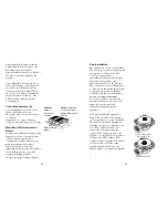
Minimum
distance
to side wall:
150 mm
Minimum distance
to back wall (non-
flammable material):
50 mm
Reinforcement
beams
13
Gas installation
The appliance is factory set for Natural
Gas. Fit the gas regulator supplied with
the appliance to the gas inlet. The
location of the gas inlet is
approximately 240mm form the right
hand side of the appliance and
40mm from the back of the appliance.
The connection of the Gas Regulator is
½” Gas female thread and the pressure
at the test point should be adjusted
to1.00kPa with the large and simmer
burners operating at maximum.
For Universal LPG connection, the
appliance needs to be first converted
using the conversion kit and
instructions supplied with the
appliance.
For Universal LPG the regulator is
fitted to the gas inlet of the appliance
so that a pressure test point is available.
The regulator should be disabled by
adjusting the regulator adjusting screw
to be fully screwed in, but do not
remove the locking nut from the
regulator. The supply pressure to the
appliance is controlled by the regulator
located on the LPG cylinder. This
cylinder regulator should be adjusted to
give a pressure of 2.75kPa at the
appliance inlet with the large and
simmer burners operating at maximum.
Adjusted for LPG
Typical Adjustment
for Natural Gas
B2004


