- 31 -
DGS-TDS-N 05.09 A. B. © Electrolux
599 518 252
EN
Fig.: HOC2000 power board built in the appliance (example built-in cooker)
The assembly position in the appliance is at the right side wall of the housing. For disassembly of
the power board you first have to remove the housing lid. Afterwards you can unscrew both screws
which fix the unit power board and plastic housing from the outside of the appliance.
Note:
A built-in cooker must be removed completely from the built-in cavity for disassembling
the power board.
Содержание Built-in appliances
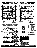
Страница 37: ... 37 DGS TDS N 05 09 A B Electrolux 599 518 252 EN 7 2 Example circuit diagram OVC 1000 ...
Страница 38: ... 38 DGS TDS N 05 09 A B Electrolux 599 518 252 EN 7 3 Example circuit diagram OVC 2000 ...
Страница 39: ... 39 DGS TDS N 05 09 A B Electrolux 599 518 252 EN 7 4 Example circuit diagram SOEC ...
Страница 40: ... 40 DGS TDS N 05 09 A B Electrolux 599 518 252 EN 7 5 Example circuit diagram Prisma ...
Страница 41: ... 41 DGS TDS N 05 09 A B Electrolux 599 518 252 EN 7 6 Example circuit diagram HOC 2000 ...
Страница 42: ... 42 DGS TDS N 05 09 A B Electrolux 599 518 252 EN 7 7 Operative Equipment Overview ...
Страница 43: ... 43 DGS TDS N 05 09 A B Electrolux 599 518 252 EN Changes Pages 34 Chapter 6 1 changed ...


