

6.
1
XBM10 GB 02 07
6
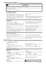
5.3 BLOCKAGE OF A TOOL ON THE TOOL HOLDER SPINDLE
- By tapping The tool with A mallet after clearing The pin from
The bayonet.
- Rub down the distorted part where necessary.
If the problem persists contact your supplier’s service
department.
• Generally due to poor cleaning or a distorted tool bore caused
by a blow.
• If the tool is starting to seize, do not force it. Apply oil or pe-
netrating fluid and wait a few minutes for the product to work.
• Work it gradually, applying measured force:
- Turning it, using a to-and-fro movement.
5.4 RAISING AND LOWERING SYSTEM
• If the lever for raising and lowering becomes difficult to operate :
- Check if the 2 rods supporting the cradle have not suffered
any impacts. Smooth with abrasive cloth if necessary.
- Lightly oil the two posts with Vaseline.
- If necessary, remove the top cover and lightly oil the upper
parts of the two rods and the hinge pins.
5.5 SPEED CONTROL LEVER
• If the speed control lever becomes hard:
- lightly oil the variable pulleys and grease the sliding gear
drive pin.
• If the lever self-maintenance system is no longer working, refer
to § 6-3 speed adjustment.
If the problem persists contact your supplier’s service
department
.
Maintenance
ATTENTION!!
Maintenance may only be carried out by a qualified, trained and authorised person
6.1 MECHANICAL PARTS
• At least once a year it is recommended to:
- If necessary, grease the planetary gears with a high adhesive
grease (ask us, see § 6-4).
- Clean out the belt dust and flour from inside the machine using
a vacuum cleaner.
• Access to electrical components:
- disconnect the machine.
Residual voltage at the capacitor terminals
• The capacitors may still have an electric charge. In order to avoid
any risk when carrying out an intervention, it is recommended to
discharge them by connecting their terminals using an insulated
conductor (e.g. screwdriver).
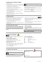
6.2 CHANGING THE BELT
- Stop the beater in high speed (position 8) and unplug it.
- Remove the screws from the upper cove and disconnect it to
separate it from the head.
- Put the lever to the min. speed position (No. 1).
- Then put the lever to the max. speed position (No. 8).
- Disengage the belt from the driven pulley.
- Hold the belt on the side and pull towards you until it releases
from the variable drive pulley.
To fit the new belt:
- Present the belt onto the drive pulley.
- Pull firmly to engage it as far as possible.
- Engage the belt on the driven pulley.
- Turn the driven pulley by hand to even out the position of the
belt.


