


Wiring
3-17
IQ 2000/5000 Installation Manual
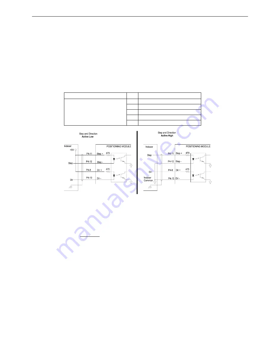
Step and Direction Inputs
Figure 3.15 illustrates connections of the PDM, which can accept step and direction inputs on
P4. These inputs provide a standard interface to an indexer. If the step and direction inputs on
P4 are used, the encoder 2 port may still be used as encoder 1 out, but not for connections to an
auxiliary encoder input. The step and direction inputs require a source to drive a 10 mA load
at 5 VDC. TTL levels are compatible as long as the input current is sufficient. These optically
isolated inputs are suitable for open-collector drivers on the inputs. The source of the step and
direction signals must provide power for the opto-isolators as well as step and direction signals.
The figure below illustrates the connections for active high and active low signals to the step
and direction inputs.
T
ABLE
3.11
Step and Direction Inputs and Signal Name
The input resistance provides the proper current limit for a +5 VDC signal. External resistance
in series with the step and direction lines to limit current to 10 mA allows operation with voltages
greater than 5 Volts.
The step input is active low and will accept a square wave input with a maximum frequency of
800 kHz. The direction input is high for motion in the forward direction. The direction input
should change a minimum of 4 microseconds before the first step pulse in that direction.
The distance moved given an input of N step pulses is a function of the software gear ratio set
in the PDM. The number of encoder counts moved is:
The signal wires from the indexer should be shielded, and the shield connected to the chassis
of the device generating the signals. In some cases it may be necessary to connect the shield at
the PDM end of the cable, at P4-15.
Connector
Pin Signal Name
P4
Encoder Input 2
8 DIR+
11 STEP+
12 STEP-
13 DIR-
15 Shield
F
IGURE
3.15
Step and Direction Input Connections
Intro
Re =
Vcc
Re
External Resistance (k
Vcc
Signal Voltage
−
−
=
=
18
10
0 470
.
.
)
Ω
Содержание IQ 2000
Страница 8: ...Intro 6 Contents P N 0013 1027 005 Rev A ...
Страница 48: ...2 30 Installation P N 0013 1027 005 Rev A FIGURE 2 23 IQ 5000 Transformer Load Regulation Curve ...
Страница 49: ...Installation 2 31 IQ 2000 5000 Installation Manual FIGURE 2 24 PSM AUX Outline and Connection Diagram ...
Страница 51: ...Installation 2 33 IQ 2000 5000 Installation Manual FIGURE 2 26 IQ 2000 Transformer Load Regulation Curve ...
Страница 53: ...Installation 2 35 IQ 2000 5000 Installation Manual FIGURE 2 29 24V Sourcing I O Conversion Card ...
Страница 54: ...2 36 Installation P N 0013 1027 005 Rev A ...
Страница 79: ...Wiring 3 25 IQ 2000 5000 Installation Manual 3Wiring FIGURE 3 25 IQ 5000 Power Wiring ...
Страница 80: ...3 26 Wiring P N 0013 1027 005 Rev A FIGURE 3 26 PSM AUX Connections ...
Страница 81: ...Wiring 3 27 IQ 2000 5000 Installation Manual FIGURE 3 27 IQ 2000 Power Wiring for PDM 10 20 and 30 ...
Страница 82: ...3 28 Wiring P N 0013 1027 005 Rev A FIGURE 3 28 IQ 2000 Power Wiring for PDM 75 ...
Страница 88: ...3 34 Wiring P N 0013 1027 005 Rev A ...
Страница 94: ...4 6 Applying Power for the First Time P N 0013 1027 005 Rev A ...
Страница 104: ...6 4 Specifications P N 0013 1027 005 Rev A ...
Страница 114: ...Help 6 EU Directives P N 0013 1027 005 Rev A ...


