This last condition is the key to all line array analysis, at
least from a theoretical standpoint. Subsequent discussions of
the line array performance will demonstrate what this condition
of equal magnitude and phase rarely, if ever, occur..
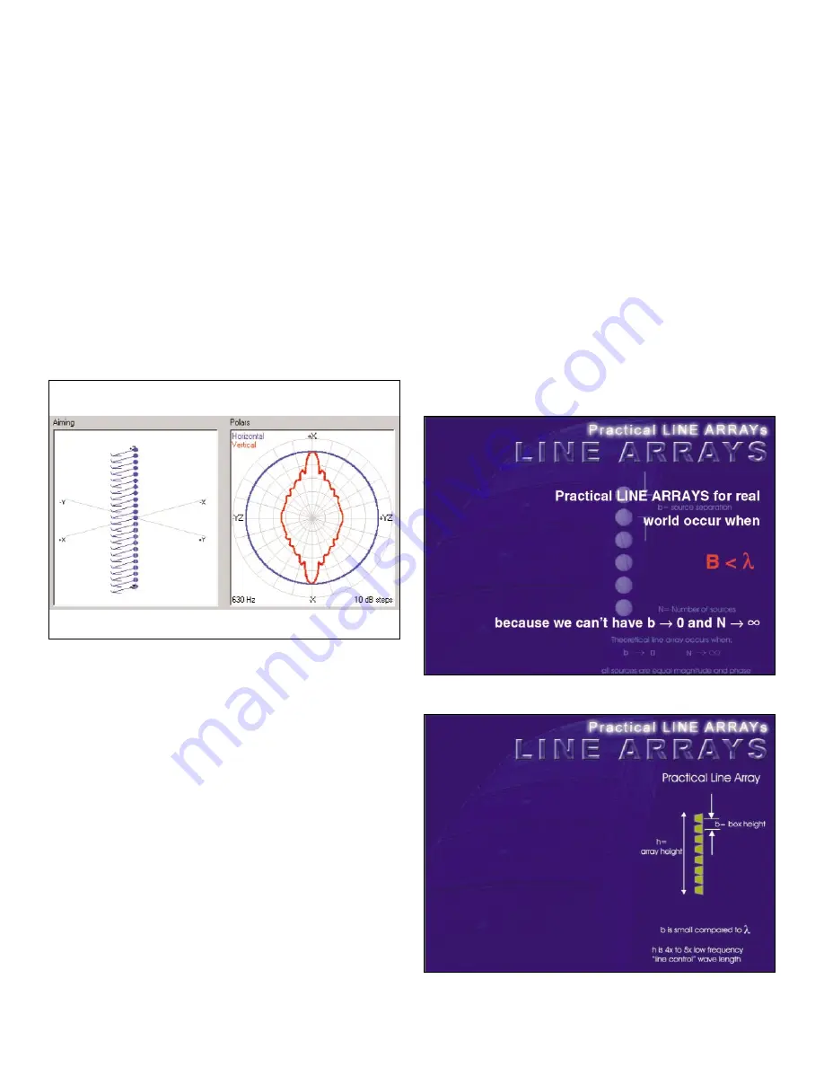
Figure 16
shows a theoretical line array with a large number of vertically
oriented sources. The radiation frequency associated with this
figure is 630 Hz. Examination of the polar pattern shows very
controlled response with very minimal lobing error. Appropriate
examination of this polar for a line array is in the quadrant
from +x to –y (in the Array Show plot). This is the section of
any line array that is used for audience coverage.
Given the definition of the line arrays previous discussed,
we can now begin to look at practical line arrays and their
applications. As noted, we cannot achieve source separation
approaching 0 nor the number of sources approaching infinity.
Practical line arrays or those realizations of line arrays occur
when the space in B is less than the radiated wavelength.
Figure 17
is a key design consideration when designing a full
bandwidth line array system. Practical line arrays not only
require that the radiating elements separation ”B” be less than
the wave lengths radiated for those devices, but subsequent
spacing of cabinets is also required to be very small compared
to the wave-lengths.
In
Figure 18,
we see a linear arrangement of 8 cabinets.
We have another spacing constant B’ that is required to be very
small. In addition, the line array overall height H must be large
compared to the radiated wavelengths. The device separation B
and line array height H are two key parameters to describe
both the high frequency limits (fmax) and low frequency limits
(fmin) of a line array system. The space B helps to determine
Fmax, the highest frequency of well-behaved summing. The
parameter H defines Fmin, the lowest frequency that the line
array can maintain a constant directivity versus frequency.
As previously noted, the space in B’ (the space between enclo-
sures) must always be less than a wavelength. The array height
H must always be at least 4 to 5 times longer than the longest
frequency of radiation to achieve constant directivity index
versus frequency.
As we will see in subsequent discussions, these two
parameters are the key parameters controlling our overall line
array performance and its bandwidth. As can be seen from
examination of the previous slides, physical orientations of
radiating sources can produce improved directional response.
The improvements in Q and associated directivity index gains
are simply the result of the fact that the radiating sources
(all of the same amplitude and phase) are separated physically
in space and hence the arrival of signals at any given point in
space are at different times and result in either constructive
or destructive addition (peaks and dips in response).
The constructive addition, of course, is the desire of the
system’s designer and understanding the destructive addition
(dips, or cancellation) is necessary in order to fully optimize
the overall system’s results. It has been seen that directional
radiation can be achieved by orientation of simple sources.
Figure 16
Figure 17
Figure 18
5


