- 26 -
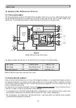
• As better explained in section 12.4, the MUX can tolerate one or more short-failed input capacitors while still
working properly, the probability of loop interference is also very low for a wide range of internal MUX faults.
The MUX input isolation was designed to allow the highest flexibility in connecting the channels to sense the HART
signal. The max 30 Vdc input voltage (specified between all terminals, both belonging to the same channel or not)
makes it possible to connect any MUX terminal to whatever voltage level can be derived from a 24 Vdc supply,
+20% tolerance included.
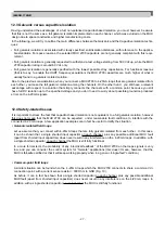
The input-channels isolation specifications for the MUX 2700 are summarised in the following table:
IM-ENG-116/GB
Channel number:
32 signal loops (64 terminals)
Channel isolation technique:
capacitor isolation, 2 capacitors for each loop
+ terminal capacitor:
0.68 µF, 63V polyester capacitor (non-polarised)
- terminal capacitor:
2.2 µF, 50V non-polarised electrolytic capacitor
Allowed common mode voltage:
up to 30V
Max input common-mode voltage:
30 Vdc
(between terminals of different channels)
Max input differential-mode voltage:
30 Vdc
(between terminals of the same channel)
Common mode internal clamping:
+/- 10V (for transient or AC signals)
(between terminals of different channels)
Differential mode internal clamping:
+/- 5V (for transient or AC signals)
(between terminals of the same channel)
MUX 2700 I
NPUT
I
SOLATION
S
PECIFICATIONS
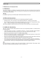
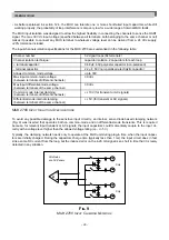
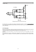
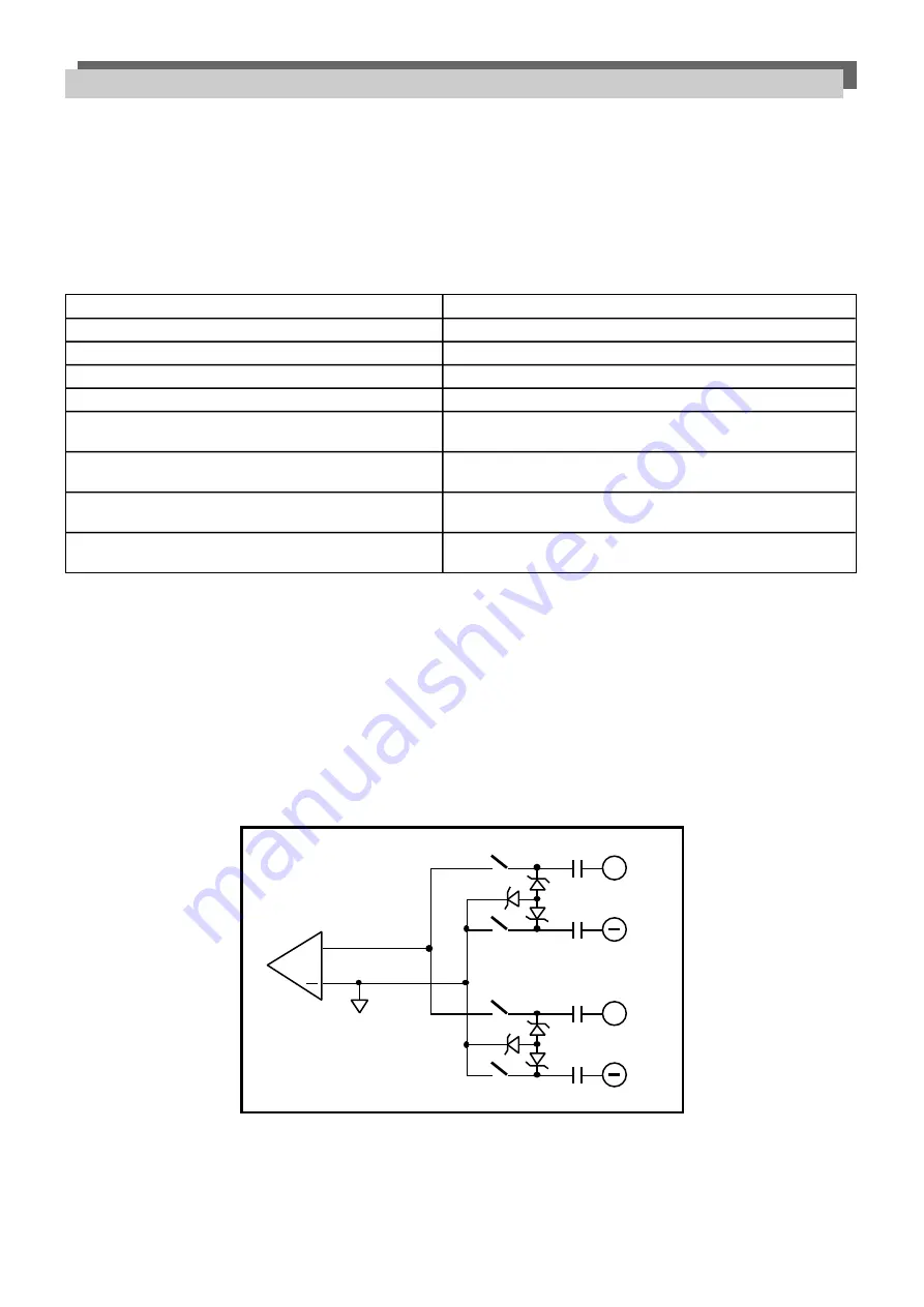
To avoid any possible damage to the sensitive input circuitry, an internal, zener-diode based clamping network
(Fig. 9) was inserted that operates both on common-mode and on differential-mode transients. This is required
because, for relevant input transient or AC signals, the input capacitors could momentarily couple to the input cir-
cuitry with a voltage level higher than the allowed voltage rating (i.e., +/- 5V).
Typically, the clamping network needs only to operate at the MUX unit during plug-in time, when the input capaci-
tors are initially charged. During the capacitors charge time (typically less than 1 ms) the input circuit does in fact
sink a some DC current from the loop, but the induced error on the 4-20 mA signal is so short in time that it is rarely
detected in any situation.
All diodes
are 5V Zeners
A
+
+
CHx
+
CHy
F
IG
. 9
MUX 2700 I
NPUT
C
LAMPING
N
ETWORK

