background image

1

en

This product meets the Electromagnetic Compatibility Directive.
The product is Class A, Group 1 ISM equipment according to CISPR 11
Group 1 ISM product: A product in which there is intentionally generated and/or used conductively
coupled radio-frequency energy which is necessary for the internal functioning of the equipment
itself.
Class A product are suitable for use in all establishments other than domestic and those directly
connected to a low voltage power supply network which supplies buildings used for domestic
purposes.

Note:


In the close presence of some radio transmitters, erroneous readings may be given. If this

occurs tests should be repeated at another location.

These operating instructions are available for download on our website www.elcometerndt.com.

The following trademarks are registered trademarks of Elcometer Limited, Edge Lane, Manchester,
M43 6BU. United Kingdom:


Material Safety Data Sheets for the ultrasonic couplant supplied with the CG70ABDL & CG70BL
and available as an accessory, are available to download via our website:

Elcometer NDT Ultrasonic Couplant Material Safety Data Sheet :

www.elcometerndt.com/images/MSDS/elcometer_ultrasonic_couplant.pdf

Elcometer NDT Ultrasonic Couplant Material Safety Data Sheet :

www.elcometerndt.com/images/MSDS/elcometer_ultrasonic_couplant_hi_temp.pdf

All other trademarks acknowledged. © Elcometer Limited 2011/2012. All rights reserved. No part of
this document may be reproduced, transmitted, transcribed, stored (in a retrieval system or
otherwise) or translated into any language, in any form or by any means (electronic, mechanical,
magnetic, optical, manual or otherwise) without the prior written permission of Elcometer Limited.

TMA-0552 Issue 01

Text with cover: 23708

Содержание CG70ABDL

Страница 1: ...0 en Models CG70ABDL CG70BDL Corrosion Gauge Operating Instructions...

Страница 2: ...terndt com The following trademarks are registered trademarks of Elcometer Limited Edge Lane Manchester M43 6BU United Kingdom Material Safety Data Sheets for the ultrasonic couplant supplied with the...

Страница 3: ...nt Measurement Technique 14 11 Measurement Options 14 12 Flaw Mode CG70ABDL only 16 13 Measurement Recording your Readings 17 14 Gauge Setups 19 15 Data Transfer Software 20 16 Storage 21 17 Maintenan...

Страница 4: ...allows readings to be stored in batches before being downloaded to a computer Note Some functions are only applicable to certain models and these are highlighted throughout this Instruction Manual 1...

Страница 5: ...s or functions Clears a measurement from a log file cell location or set obstruct and back space in an Alpha Edit Box Press to start taking measurements Scroll forwards through the hot menu Press to c...

Страница 6: ...thickness of the material being measured The transducer connects to the gauge via the attached cable and two coaxial connectors When using transducers manufactured by Elcometer the orientation of the...

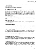
Страница 7: ...The menus can be displayed in English Spanish and German 1 Select MENU SETUP LANGUAGE and adjust 5 THE MEASUREMENT SCREEN Your gauge has up to four types of measurement screen A Scan Waveform RF CG70A...

Страница 8: ...gauge is reliably measuring the value C Material Thickness Value Material Velocity Value The thickness or sound velocity of the material under the transducer type depends upon measurement view D Unit...

Страница 9: ...ring the process the scan bar will quickly deflect and alarm you to go back and search for the defect 5 5 DIGITS MEASUREMENT SCREEN The digits display shows the thickness as a value using a large font...

Страница 10: ...riety of applications To obtain valid readings the gain must be set to the correct level to give reliable return echoes Too much gain may result in erroneous measurements by detecting noise rather tha...

Страница 11: ...mode press MULTI MODE until the correct mode is displayed or select MENU GATE MEASURE MODE Note The availability of the modes depends upon the type of transducer fitted to the gauge 6 1 PULSE ECHO MOD...

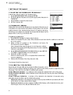
Страница 12: ...ng these steps to ensure reliability of the zero calculation 4 Select MENU PROBE ZERO TRANSDUCER and press ENTER The ZERO TRANSDUCER screen is displayed 5 Press OK or ESC to cancel When the manual pro...

Страница 13: ...velocity Note Although the gauge has a ThruPaint coating feature known thickness calibration must be performed on material with the paint or coating removed One point Calibration The one point calibr...

Страница 14: ...rrect measurement mode see Measurement Modes on page 10 Set the zero point of the transducer see Transducer Zeroing on page 11 and Calibrate the gauge see Calibrating for a Material on page 11 and Cho...

Страница 15: ...ATE 10 THRUPAINT MEASUREMENT TECHNIQUE 10 1 INTRODUCTION Your gauge is equipped with a ThruPaint measurement mode that uses a multiple echo technique to allow measurement of the material thickness ben...

Страница 16: ...rm Mode 1 Select MENU UTIL ALARM STATUS 2 Use the LEFT and RIGHT arrows to toggle the ALARM on off audible 3 Press MEAS to return to the measurement screen ready to begin taking readings To set the Al...

Страница 17: ...formation on flaw detection can be found on the Elcometer NDT Knowledge Centre on www elcometerndt com 12 2 FLAW MODE VIEW 12 3 ENABLING FLAW MODE To use Flaw Mode an angle beam transducer and dual le...

Страница 18: ...following characters can be used for file names Numeric characters 0 9 Alpha Characters A Z Special Characters _ space What measurement data is saved When a measurement is taken irrespective of log fi...

Страница 19: ...save a new reading to the same location refer to the instructions given in Viewing and Deleting readings on page 18 3 Take a reading and then press ENTER The reading value is saved in the file at the...

Страница 20: ...lete all the data logger files in gauge memory use with caution 1 Select MENU DATA DELETE ALL GRIDS 2 Press ENTER and then OK to confirm or ESC to cancel The data logger memory is erased all files are...

Страница 21: ...isplayed 5 Scroll through the list of setups until the required location to save the setup is highlighted 6 Press OK to activate the confirmation screen 7 Press OK to save the SETUP or ESC to cancel N...

Страница 22: ...ress the MEAS key once to return to the menu items or twice to return to the measurement mode 16 STORAGE Your gauge has a Liquid Crystal Display If the display is heated above 50 C 120 F it may be dam...

Страница 23: ...25 to 9 999 Echo Echo E E 2 54 mm to 102 mm 0 1 to 4 0 Range will vary depending on the coating Measurement Resolution Sound Velocity 1 m s 0 0001 in s Thickness 0 01 mm 0 001 Velocity Calibration Ran...

Страница 24: ...a re manufactured unit Replace the product with a product of equal or greater performance Refund the purchase price 19 3 AFTER THE WARRANTY PERIOD If your hardware should fail after the warranty peri...

Страница 25: ...Titanium Block 20 3 ULTRASONIC COUPLANT Each gauge is supplied with a 120ml 4oz bottle of standard ultrasonic couplant Replacement bottles and couplant for high temperature applications are available...

Страница 26: ...56 Iron 5893 0 232 Tin 3327 0 131 Lead 2159 0 085 Titanium 6096 0 240 Magnesium 5791 0 228 Tungsten 5334 0 210 Mercury 1448 0 057 Water 1473 0 058 Nickel 5639 0 222 Zinc 4216 0 166 Nylon 2591 0 102 Ap...

Страница 27: ...CONTRAST Adjusts the contrast of the display BACKLIGHT Select backlight option of OFF ON or AUTO In AUTO mode the backlight is only switched on when the gauge is making a measurement TUNE POLARITY The...

Страница 28: ...mode ON OFF or AUDIBLE ALARM HIGH Sets the HI limit parameter If the measurement exceeds this value a red light will illuminate and the alarm will sound ALARM LOW Sets the LOW limit parameter If the m...

Страница 29: ...n 12 M Measurement Modes 10 Measurement Procedure 13 Measurement Screens 7 Memory 17 O One Point calibration 11 P Packaging 4 Peak 17 Polarity 15 Probe Zero 11 Pulse Echo P E 10 Pulse Width 15 Pulse E...

Отзывы: