


03/2013 - Art. Nr. 4200 1032 7200A
14
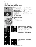
Ionisation current measurement
To measure the ionisation current,
disconnect connector
B10
and connect
a multimeter with a measuring range of
0-100 µA.
The ionisation current must be at least
8 µA. It is also possible to read the
ionisation current on the display.
All electrical installation and
connection work must only be carried
out by a suitably qualified electrician.
The applicable guidelines and
directives must be observed,
as well as the electrical circuit
diagram supplied with the
burner!
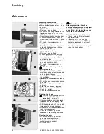
Electrical connection
• Check to ensure that the power supply
is as specified (230V, 50 Hz single
phase with neutral and earth)
Boiler fuse: 6.3 A
The burner motor has its own
separate power supply (no. 3).
Fuse on the motor circuit: 6 A gM
Electrical connection
It must be possible to disconnect
the burner from the mains using an
omnipolar shutdown device
complying with the standards in
force. The burner and heat
generator (boiler) are connected
by a 7-pin connector
1
and a 4-pin
connector
2
(
not supplied
). The
diameter of the cables connected
to these connectors must be
between 8.3 and 11 mm.
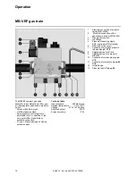
Connecting the gas train
Connect the gas train to the plugs on the
burner (black to black, grey to grey).
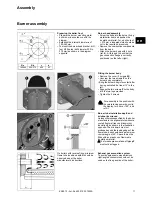
Assembly
Gas connection
Electrical connection
Checks before commissioning
General regulations applying to the
gas connection
• The gas train must only be connected
to the gas mains by a recognised
specialist.
• The cross-section of the gas line
should be of a size designed to
guarantee that the gas flow pressure
does not drop below the specified
level.
• A manual shut-off valve (not supplied)
must be fitted upstream of the gas
train.
• In Germany, a thermally triggered
shut-off valve (to be installed by the
customer side) must be fitted as
specified by the draft combustion
ordinance.
It is the responsibility of the fitter or his
representative to obtain approval for the
system at the same time as the burner is
commissioned. Only the fitter or his
representative can guarantee that the
system meets applicable standards and
regulations. The fitter should be in
possession of the corresponding official
permit, and should carry out the
corresponding sealing tests and purge
the system of air.
Checks before commissioning
The following must be checked before
initial commissioning:
• That the burner is assembled in
accordance with the instructions given
here.
• That the burner is pre-set in
accordance with the values in the
adjustment table.
• Setting the combustion components.
• The heat generator must be ready for
operation, and the operating
regulations for the heat generator
must be observed.
• All electrical connections must be
correct.
• The heat generator and heating
system must be filled with water and
the circulating pumps must be in
operation.
• The temperature regulator, pressure
regulator, low water detectors and any
other safety or limiting devices that
might be fitted must be connected and
operational.
• The exhaust gas duct must be
unobstructed and the secondary air
system, if available, must be
operational.
• An adequate supply of fresh air must
be guaranteed.
• The heat request must be available.
• Sufficient gas pressure must be
available.
• The fuel supply lines must be
assembled correctly, checked for
leaks and bled.
• A standard-compliant measuring point
must be available, the exhaust gas
duct up to the measuring point must
be free of leaks to prevent anomalies
in the measurement results.
Содержание VG4.460 DP
Страница 29: ...03 2013 Art Nr 4200 1032 7200A 29...
Страница 30: ...03 2013 Art Nr 4200 1032 7200A 30...
Страница 31: ...03 2013 Art Nr 4200 1032 7200A 31...


