03/2013 - Art. Nr. 4200 1032 7200A
13
en
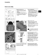
Checking the burner head
• Check the adjustment settings of the
ionisation probe and of the ignition
electrode as per the diagrams.
Setting to liquid gas operation
• Remove the gas diffuser
5
and the
turbulator
2
.
• Remove adaptor
3
.
• Fit the adaptor
6
(supplied with the
housing) on the gas burner head.
• Turn the gas diffuser
5
180° and refit it.
• Refit the turbulator
2
and the 3 spacers
4
, using the 3 new screws
1
provided.
Assembly
Checking/adjusting the burner head
Check the radial position of the flame
tube
After untightening the three mounting
screws
S
, it is possible to change the
position of the flame tube using the lever
H
. Nitrogen oxide emissions may be
affected by the radial position of the
flame tube
• To be set at the start to position 1.
Fitting the combustion components
• Check that the O-Ring
J1
is in the
correct position in the gas elbow.
• Insert the combustion components
into the head, tighten the mounting
screw
X
using an Allen key, then
tighten the lock nut using an open-
ended spanner.
• Thread the ionisation cable
IK
and the
ignition cables
ZK
into the grommets
R
and
S
.
• Remove the cover.
Содержание VG4.460 DP
Страница 29: ...03 2013 Art Nr 4200 1032 7200A 29...
Страница 30: ...03 2013 Art Nr 4200 1032 7200A 30...
Страница 31: ...03 2013 Art Nr 4200 1032 7200A 31...


