background image


Bedienungsanleitung 

Manual 

MAN_FIMP XL-E 

Version:  1.0.8 

/ 13.11.2020 

Freigabe: 

U.A. 

Seite 3 von 9 


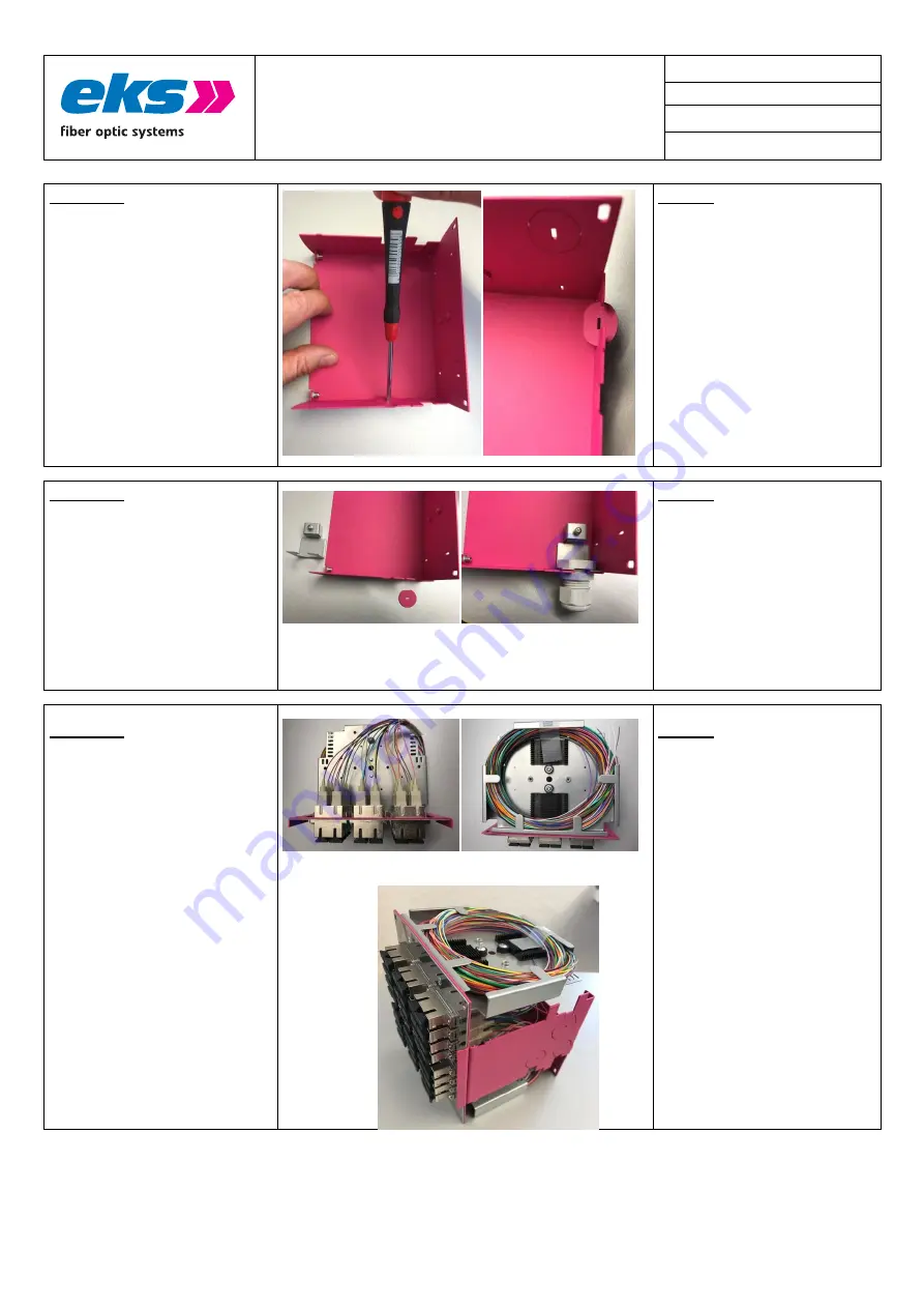
Schritt 3 

 
  Für den Einbau der Kabelverschraubung 

müssen Sie die Lasche wie im Bild 
dargestellt herausbrechen. 

 
  Benötigen Sie weitere Kabeleinführungen, 

so brechen Sie auch die entsprechenden 
vorgelaserten Öffnungen im Gehäuse aus. 

 
  Die  breite  Schale  ist  für  M20  Druchbrüche 

gelasert, die schmalen Schale für M25. 


Step 3 

 
  To install the cable gland, you must 

break out the tab as shown on in the 
picture. 

 
  If you need further cable entries, break 

out the corresponding pre-lasered 
openings in the housing. 

 
  The wide shells are lasered for M20 

breakthroughs, the narrow shells for 
M25. 


Schritt 4 

 
  Befestigen Sie anschließend die 

Kabelverschraubungen im Gehäuse. 

 
  Führen Sie die Kabel durch die 

Kabelverschraubungen und manteln Sie 
diese in der gewohnten Weise ab. Die 
abisolierte Länge sollte ca. 1,5 m sein. 

 
  Möchten Sie zusätzlich die Zugenlastung 

M20 wie rechts im Bild dargestellt 
einbringen, so können Sie diese optional 
mit der Artikelnummer 1060000013 
bestellen. 


Step 4 


  Fasten the cable gland to the case. 
 
  Please insert the cable into the 

cablegland and dismantle it in the usual 
manner. The dismantled length should 
be approximately 1.5 m. 

 
  If you like to use an extra strain relief for 

M20 as shown in the picture on the left, 
you can separetly with order no. 
1060000013. 


Schritt 5 

 
  Kontrollieren Sie, dass die Faser-Pigtails 

nicht beschädigt sind. 


Step 5 


  Check that the fiber pigtails are not 

damaged. 


Stellen Sie das Zwischenstück mit den 
Pigtails und den Spleisskassetten auf eine 
ebene Unterlage, so das Sie in den 
nächsten Arbeitsschritten den 
Spleissvorgang durchführen können. 


  Place the main corpus with the pigtails 

and the splice cassettes on a flat surface 
so that you can carry out the splicing 
process in the next steps. 


Содержание FIMP XL-E

Страница 1: ...ung zu ernsthaften Personen oder Anlageschäden führen kann Bitte lesen Sie die Anleitung vor Inbetriebnahme des Gerätes aufmerksam durch Ord nungsgemäßer Transport korrekte Lagerung und Installation sowie sorgfältige Bedienung und Instandhaltung des Geräts sind entscheidend für den sicheren Betrieb This manual contains important notes and warnings which if ignored can lead to serious personal inju...

Страница 2: ...with up to four splice holders This makes it possible to connect up to 48 fibers The sturdy metal housing is made of stainless steel powder coated has two clips for 35 mm DIN rail mounting and measures only 140 x 137 x 137 mm width x height x depth FIMP XLE is available for plastic fibers POF HCS multimode and singlemode Montagehinweise Mounting Schritt 1 Öffnen Sie die Verpackung und kontrolliere...

Страница 3: ...ln Sie diese in der gewohnten Weise ab Die abisolierte Länge sollte ca 1 5 m sein Möchten Sie zusätzlich die Zugenlastung M20 wie rechts im Bild dargestellt einbringen so können Sie diese optional mit der Artikelnummer 1060000013 bestellen Step 4 Fasten the cable gland to the case Please insert the cable into the cablegland and dismantle it in the usual manner The dismantled length should be appro...

Страница 4: ...Länge verwendet werden Dann benötigen Sie den optional erhältlichen Spleißkamm für Schrumpfspleißschutz Artikelnummer 1060000019 Dieser ist geeignet für 6 Schrumpfspleiß schutze mit 3 mm Durchmesser Die Länge von 45 mm sollte nicht überschritten werden Fiber guide and bending radius Two splice holders can be installed on each side to hold up to 24 pigtails per side Note Standard scope of delivery ...

Страница 5: ...r must be damaged when assembling the housing shells Schritt 10 Montieren Sie die Gehäuseschale rechts mit zwei Linsenflanschkopfschrauben an der Frontplatte Step 10 Mount the right housing shell to the front panel using two allen pan head screws Mit zwei weiteren Linsenflanschkopf schrauben befestigen Sie die Gehäuseschale rechts am Zwischenstück im rückwärtigen Bereich Fasten the housing shell o...

Страница 6: ...n nicht mehr gewährleistet werden Step 12 Mounting on DIN Rail For mounting see picture on the left please snap the FIMP XLE on the top side into the DIN rail and then press down against the spring force 1 and then towards the mounting plate 2 The FIMP XLE system locks as shown in the picture on the right To remove press the housing down overcome the spring force of the DIN rail clip then pull the...

Страница 7: ... 06180 0 36212 36212 9 00 06180 0 37012 37012 9 00 06180 0 38312 38312 9 00 06180 0 36406 36406 9 00 06180 0 38406 38406 9 00 Faser Fiber Single Mode 9 125µm LWL Anschluss Fiber connector ST SC SC APC LC LC APC Einfügedämpfung Insertion loss Multimode 0 3 dB Singlemode 0 2 dB Kabelzuführung Cable entry Verschraubung M20 max Kabeldurchmesser 13 8 mm M25 max Kabeldurchmesser 21 mm Cable Gland M20 fo...

Страница 8: ... MM 0600 E 142 05 Kabelverschraubung Cable gland M20 106 000 000 1 Gegenmutter Lock nut M20 106 000 000 2 Kabelverschraubung Cable gland M25 106 000 000 4 Gegenmutter Lock nut M25 106 000 000 5 Spleißkamm Splice holder 106 000 002 2 Spleißschutz Splice protection 106 000 002 3 Kabelbinder Cable tie 100x2 5 mm 106 000 000 8 Schraube Screw zur Montage der Frontplatte for mounting the frontpanel 100 ...

Страница 9: ...ect to technical changes No liability for errors and misprints eks Engel FOS GmbH Co KG Farbcode gemäß DIN EN 60794 1 1 Beiblatt 1 2014 04 Code according to DIN EN 60794 1 1 supplementary sheet 1 2014 04 Multiple sealing insert Mehrfachdichteinsatz Multiple sealing insert M25 3x7 mm 106 000 000 7 Zugentlastung Cable clamp M20 106 000 001 3 Schrumpfspleissschutz Shrink splice protector 106 000 001 ...

Отзывы: