25
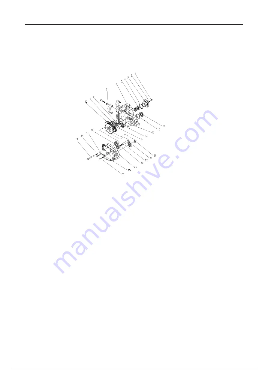
4.2 Transmission diagram
The gearbox is partially located between the drive axle and the travelling motor, and the
mechanism's two pairs of cylindrical helical gears reduce the speed from the travelling
motor's output shaft and increase the torque from the transmission shaft, which is then
transmitted to the differential. Maintenance: permanent lubrication of rotary platform
。
1.Bolt 2. Gasket 3. Bearing cover 4. O-ring 5.Deep groove ball bearing 6. Box
assembly 7. Lock plate of bearing seat 8.Deep groove ball bearing 9. Gear shaft
10. Double gear 11.Oil seal 12. Elastic retainer 13. Cylindrical pin 14.Deep
groove ball bearing 15. Input shaft 16. Deep groove ball bearing 17.Spring
washer 18. Bolt 19. Bolt 20.Seal cover 21. Deep groove ball bearing 22. Shaft 23.
O-ring 24.Box cover 25. Baffle 26. Bolts
Содержание EK18A
Страница 22: ...21 3Circuit circuit diagram 3 1Electrical schematic diagram Speed mode H...
Страница 23: ...22 3 2...


