background image

- 3 - 

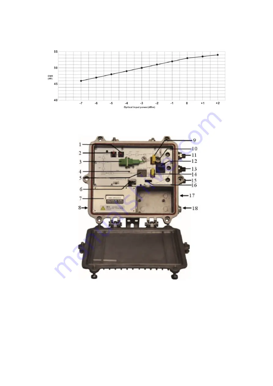
5. Relation Table of Input Optical Power and CNR

6. Structure Description

1. Adjustable ATT knob

2. Adjustable EQ knob

3. Optical receiving port (or external, optional)  4. Working indicator

5. Optical power display tube

6. Power interface

7. Switching power supply

8. Power cord in

9. AC60V power-pass inserter

10. Output -20dB test port

11. Output 1

12. FZ110 or FP204

13. AC60V feed

14. AC60V power-pass inserter

15. Output 2

16. Network management interface

17. Fiber in

18. Network cable in

Содержание XC8602ME-B

Страница 1: ...XC8602ME B Optical Receiver Manual Optical Receiver Specification ...

Страница 2: ...al according to the measuring method of GY T 194 2003 Specifications and methods of measurement on optical node used in CATV systems and tested in the following conditions Testing conditions Forward path optical receiver part with 10km standard optical fiber passive optical attenuator and standard optical transmitter composed the testing link Set 59 PAL D analog TV channel signal at range of 45 87...

Страница 3: ... CTB dB 65 C CSO dB 60 RF Parameters Frequency Range MHz 45 862 Flatness in Band dB 0 75 Rated Output Level dBμV 108 Max Output Level dBμV 116 7 2dBm optical power received Output Return Loss dB 16 Output Impedance Ω 75 EQ Range dB 0 20 ATT Range dB 0 20 Generic Characteristic Power Voltage V A AC 150 265 V B AC 35 90 V Operating Temperature 40 60 Consumption VA 18 Dimension mm 220 L 205 W 65 H No...

Страница 4: ...g port or external optional 4 Working indicator 5 Optical power display tube 6 Power interface 7 Switching power supply 8 Power cord in 9 AC60V power pass inserter 10 Output 20dB test port 11 Output 1 12 FZ110 or FP204 13 AC60V feed 14 AC60V power pass inserter 15 Output 2 16 Network management interface 17 Fiber in 18 Network cable in ...

Страница 5: ...an be direct connected and change the computer IP to 192 168 1 XXX XXX is any number from 0 to 255 except 168 start upper computer network management software then search the device and log in 3 Right click device icon and choose modify the device IP 4 Enter new IP address gateway and subnet mask 5 Click modify then exit it is done There will show new IP address and gateway on operational logbook ...

Страница 6: ... signal is too low 1 Check the received optical power of the optical contact point and make appropriate adjustments to make it in the specified range 2 Improve the optical received power of the optical contact point by cleaning the optical fiber connector or adapter etc methods Specific operation methods see Clean and maintenance method of the optical fiber connector 3 Check the RF input signal le...

Страница 7: ...nnector component or bulkhead with a fiberscope If the connector is dirty clean it with a cleaning technique following these steps 1 Carefully pull off the optical fiber active connector from the adapter The optical fiber active connector should not aim at the human body or the naked eyes to avoid accidental injury 2 Wash carefully with good quality lens wiping paper or medical degrease alcohol co...

Отзывы: