background image

E

7

                      INTRODUCTION

INTRODUCTION

About This  Manual

This manual explains the precautions, specifications, and operation of your EIZO
monitor.  Please read through this manual as it will help you to get the most out of
your monitor.

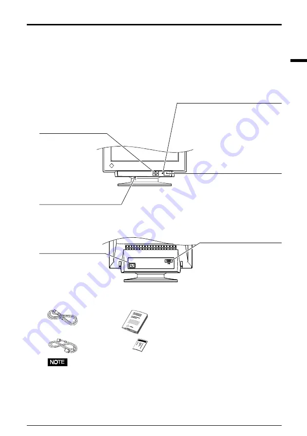
Controls & Connectors:

Front

Package Contents:

• If any of the above-listed items are missing or damaged, please contact your local

dealer for assistance.

Rear

Power connector

D-Sub mini 15 pin

input connector

QuickSet

 Control pad

(hereinafter “Control pad”)

Power terminal covers for the
optional i·Sound sound unit

Power switch

Power indicator

Indicates the power-on status, as follows:
Solid green:

Power is ON

Flashing green:

PowerManager Mode 1
Advance Notice Mode

Yellow:

PowerManager Mode 2

Flashing Yellow: Off Timer Mode

Power Cord

User’s Manual

Warranty

Registration

Card

Signal Cable

  (MD-C87/

MD-C100)

Содержание FLEXSCAN F520 -

Страница 1: ...English User s Manual Color Display Monitor FlexScan F520...

Страница 2: ...is under no obligation to hold any submitted material or information confidential unless prior arrangements are made pursuant to EIZO NANAO CORPORATION s receipt of said information Although every ef...

Страница 3: ...ly to a standard wall power outlet Location of the Caution Statements PRECAUTIONS IMPORTANT To ensure personal safety and proper maintenance Please read this section and the caution statements on the...

Страница 4: ...fore using it again Using a monitor after it has been dropped may result in fire or electric shock Keep the plastic packing bags away from children and infants Plastic bags can be dangerous To avoid d...

Страница 5: ...or equipment damage Handle with care when carrying the monitor Note that the monitor is heavier at the front than at the rear Do not move it alone Always work with another person The screen is optica...

Страница 6: ...power outlet may result in electric shock When adjusting the viewing angle of the monitor do not do so by handling the sound unit or USB hub if applicable Adjusting the monitor in this way may break t...

Страница 7: ...ing or damaged please contact your local dealer for assistance Rear Power connector D Sub mini 15 pin input connector QuickSet Control pad hereinafter Control pad Power terminal covers for the optiona...

Страница 8: ...es the shape at the connecting side After connecting secure the connection with the screw in fasteners 3 Plug the other end of the cable into the video connector on the rear of the PC Refer to the fig...

Страница 9: ...1 2 Setting the resolution The following look up table shows the maximum Non interlaced vertical refresh rates for this model with regard to standard resolutions set forth by VESA The best way to see...

Страница 10: ...to display the each adjustment setting menu 2 Use the Control pad the four Arrow keys and the ENTER key to make the required adjustments and settings Save Exit 1 To save settings and return to the Mai...

Страница 11: ...ts Side pin balance left right Side pincushion up down Tilts image sides to sides left right Expands top side bottom side shirnking the other side up down Tilts the image left right Adjusts horizontal...

Страница 12: ...the optional EIZO i Sound speaker unit will turn off Off Timer will work while PowerManager is active but there will be no advance notice before the monitor s power switches off PowerManager VESA DPM...

Страница 13: ...LED Power consumption ON Operation Green 80 W normal STAND BY Blank Green 80 of normal SUSPEND Blank Mode 1 Flashing green less than 10 W OFF Blank Mode 2 Yellow less than 3 W Off Timer What is Off Ti...

Страница 14: ...moving the Control pad To record the new setting and exit the ScreenManager press the Enter key The brightness and contrast functions are also available in the ScreenManager contrast brightness menu...

Страница 15: ...key on the keyboard or clicking the mouse The monitor may be in a power saving mode Try pressing any keys on the front panel or switch the monitor off and then on The monitor may be in Off Timer Mode...

Страница 16: ...wer percentage or 0 See page 11 Check that the signal cable is properly connected to the graphics board or PC Check that the graphics board is correctly mounted in the PC The monitor may be located cl...

Страница 17: ...moir even further Change the horizontal and vertical dimensions of the desplay area Change the selected desktop or wallpaper pattern to any solid color pattern For detailed information on how to chang...

Страница 18: ...uildup of dust water or oil on the plug may result in fire Never use thinner benzene alcohol ethanol methanol or isopropyl alcohol abrasive cleaners or other strong solvents as these may cause damage...

Страница 19: ...aker attached PowerManager Mode 1 Less than 10 W PowerManager Mode 2 Less than 3 W Input Connector D Sub mini 15 pin Recommended Resolution 1024 dots 768 lines Input Signal Sync H V Separate TTL Posit...

Страница 20: ...Level VGA 720 400 31 47 70 09 Non H Negative 0 7V p p 75 text V Positive VGA 640 480 31 47 59 94 Non H Negative 0 7V p p 75 V Negative VESA 640 480 37 50 75 00 Non H Negative 0 7V p p 75 V Negative VE...

Страница 21: ...f personal computers The labelling scheme was developed as a joint effort by the TCO The Swedish Confederation of Professional Employees Svenska Naturskyddsforeningen The Swedish Society for Nature Co...

Страница 22: ...lour generating layers of certain computer displays Cadmium damages the nervous system and is toxic in high doses The relevant TCO 99 requirement states that batteries the colour generating layers of...

Страница 23: ...ference will not occur in a particular installation If this equipment does cause harmful interference to radio or television reception which can be determined by turning the equipment off and on the u...

Страница 24: ...h Anlage III R ntgenverordnung Die in diesem Geraet entstehende R ntgenstrahlung ist durch die eigensichere Kathodenstrahlroehre ausreichend abgeschirmt Recycle Auskunft Die R cknahme dieses Produktes...

Отзывы: