


8
GB
Important!
The vibration value changes according to the area of
application of the electric tool and may exceed the
specified value in exceptional circumstances.
Keep the noise emissions and vibrations to a
minimum.
Only use appliances which are in perfect working
order.
Service and clean the appliance regularly.
Adapt your working style to suit the appliance.
Do not overload the appliance.
Have the appliance serviced whenever
necessary.
Switch the appliance off when it is not in use.
Wear protective gloves.
5. Before starting the equipment
Before you connect the equipment to the mains
supply make sure that the data on the rating plate
are identical to the mains data.
Always pull the power plug before making
adjustments to the equipment.
All covers and safety devices have to be properly
fitted before the machine is switched on.
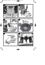
5.1 Extraction port assembly (Fig. 2/Item 1)
Important. For health and safety reasons it is
imperative that you use a dust extractor.
Connect your router to the extraction port (1) of a
vacuum cleaner or a dust extraction device. This
will provide excellent dust extraction on the
workpiece. The benefits are that you will protect
both the equipment and your own health. Your
work area will also be cleaner and safer.
Dust created when working may be dangerous.
Refer to the section entitled “Safety instructions”.
The vacuum cleaner you use for the extraction
work must be suitable for the workpiece material.
Use a special vacuum cleaner if you are handling
harmful materials.
Secure the extraction port (1) to the routing shoe
(2) using the two countersunk screws (f).
The extraction port can be connected to extractor
units (vacuum cleaners) with a suction hose.
The internal diameter of the suction port is 36
mm. Now fit a suction hose of the appropriate
size to the suction port.
5.2 Safety guard port assembly (Fig. 3/Item 13)
Fit the safety guard (13) as shown in Fig. 3.
5.3 Parallel stop assembly (Fig. 4/Item 21)
Push the guide shafts (a) of the parallel stop (21)
into the holes (b) on the routing shoe (2).
Set the parallel stop (21) to the required
dimension and secure it in place with the wing
screws (3).
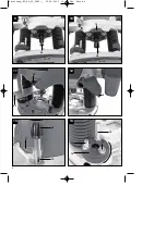
5.4 Compass point assembly (Fig. 5/Item 24)
You can cut circular areas using the compass
point (24).
Secure the compass point (24) to the parallel
stop (21) as shown in the figure. Now fit the
parallel stop (21) with the compass point (24) to
the router. The assembly work is to be carried
out as described in point 5.3, but the parallel stop
(21) must be fitted at an angle of 180° so that the
compass point (24) points downwards (Fig. 5).
Set the required radius between the compass
point (24) and cutter.
Position the compass point (24) in the center of
the circle you wish to route.
5.5 Guide sleeve assembly (Fig. 6-7/Item 25)
Secure the guide sleeve (25) to the routing shoe
(2) using the two countersunk screws (f).
The guide sleeve (25) is guided along the
template (c) using the guide ring (b).
The workpiece (d) must be larger by the
difference of “external edge of guide ring” and
“external edge of router” (e) to obtain a precise
copy.
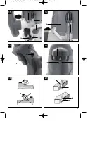
5.6 Fitting / Removing the cutting tool (Fig. 8-11)
Important. Pull out the power plug first.
Important. After working with the router, the
cutting tool will remain very hot for a relatively
long time.
Important. Cutters are very sharp. Wear
protective gloves at all times when handling
cutting tools.
Cutters with a shaft diameter of 6 mm and 8 mm
may be fitted to this router. Most cutters are
available in both sizes.
You can used cutters made of the following
materials:
-
HSS
– Suitable for machining softwood
-
TCT
– Suitable for machining hardwood,
particle board, plastic and aluminum.
Select the appropriate cutting tool for the job in
hand.
When using the cutters for the first time:
Remove the plastic packaging from the cutter
heads.
Clean the nut, clamp and shaft of the cutter
before fitting it.
Anleitung_RT_RO_55_SPK1:_ 23.04.2009 13:25 Uhr Seite 15


