7.2. Maintenance
Always switch off the machine and pull out the spark
boot plug before carrying out any maintenance work.
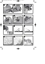
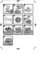
7.2.1 Replacing the line spool / cutting line
1. Unscrew the retainer screw (Fig. N1/Item A) in a
counter-clockwise direction and remove (Fig.
N1/N2).
2. Remove the spool (Fig. N3/Item B) and the spring
(Fig. N3/Item C) from the spindle (Fig. N3/Item D).
The following steps only have to be carried out if only
the line and not the entire spindle requires replacing:
Remove the remaining cutting line from the spool.
Hold the two halves of a new cutting line together
in the middle and place the loop in one of the
slots on the spool divider (Fig. N4).
Wind the line with tension in a counter-clockwise
direction as shown in the illustration (Fig. N5),
with the two halves being separated by the spool
divider. Wind up all of the line down to the last
15cm of each end.
3. Fasten each of the ends of the line in a slot (Fig.
N6/Item F) on the opposite side of the spool.
4. Fit the springs on the inside of the spool and thread
each of the ends of the line through one of the
eyelets in the spool holder (Fig. N3/Item E).
5. Insert the spool in the spool holder. Make sure that
the spring slides over the spindle and does not get
stuck.
6. Press the spool into the spool holder with your
hand and use your other hand to fasten the retainer
screw tightly (Fig. N7).
7. Give each end of the line a strong tug to pull the
line out of the slots.
8. Cut off all excess line to reduce it to approx. 13 cm.
This will reduce the load on the engine when
starting up and warming up.
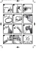
7.2.2 Maintenance of the air filter (Fig. J1-J3)
Soiled air filters reduce the engine output by supply
too little air to the carburetor.
Regular checks are therefore essential. The air filter
should be checked after every 25 hours of use and
cleaned if necessary. If the air contains a lot of dust,
the air filter should be checked more frequently.
1. Remove the air filter cover (Fig.J1-J2)
2. Remove the filter element (Fig. J3)
3. Clean the filter element by tapping it or blowing
it.
4. Assemble in reverse order.
Please note:
Never clean the air filter with petrol or
inflammable solvents. Clean the air filter with
compressed air or by tapping it.
7.2.3 Maintenance of the spark plug (Fig. K1-K3)
Spark plug gap = 0,6 mm. Tighten the spark plug
with a torque of 12-15 Nm.
Check the spark plug for dirt and grime after 10
hours of operation and if necessary clean it with a
copper wire brush. Thereafter service the spark plug
after every 50 hours of operation.
1.
Remove the spark plug cover
2.
Pull off the spark plug boot (Fig. K2) by twisting.
3. Remove the spark plug (Fig. K3) with the
supplied spark plug wrench.
4. Assemble in reverse order.
7.2.4 Grinding the safety hood blade
The safety hood blade (Fig. L/Item 1) can become
blunt over time. When you notice this, undo the two
screws holding the safety hood blade to the safety
hood. Clamp the blade in a vise. Sharpen the blade
with a flat file and make sure that the angle of the
cutting edge is not altered in the process. File in one
direction only.
7.2.5 Carburetor settings
Important.
Settings on the carburetor may only be
made by authorized customer service personnel.
The air filter cover must be removed before any work
on the carburetor, as shown in Figures J-J2.
Setting the throttle cable:
If the maximum speed of the machine falls over time
and you have ruled our all the other causes listed in
section 9 Troubleshooting, it may be necessary to
adjust the throttle cable.
First of all check whether the carburetor opens fully
when the throttle handle is pressed fully. This is the
case if the carburetor slide (Fig. 01/Item 1) rests
against the stop (Fig. 01/Item 2) when the throttle is
fully open. Figure 16 shows the correct setting. If the
carburetor slide does not touch the stop, it must be
adjusted.
The following work is required to adjust the throttle
cable:
Undo the lock nut (Fig. O2/Item 3) a few turns.
Undo the adjusting screw (Fig. O3/Item 4) until
the carburetor slide rests against the stop when
the throttle is fully open, as shown in Figure O1.
Retighten the lock nut.
Setting the idling speed:
Important.
Set the idling speed when the machine is
warm.
11
GB
Anleitung_BG_PT_3041_SPK1:_ 16.11.2010 11:13 Uhr Seite 21
Содержание 34.018.13
Страница 5: ...5 J1 J3 J2 K1 K3 K2 L M2 M1 1 2 M3 N1 M4 Anleitung_BG_PT_3041_SPK1 _ 16 11 2010 11 13 Uhr Seite 5 ...
Страница 15: ...EH 04 2012 02 ...
Страница 16: ...EH 04 2012 02 ...


