-85-
Electrical Adjustment
⁄2
Wind sensor calibration
1. Enter the service mode.
2. Select Group “
240
” and No. “
2
”. Confirm the Data
value is “
1
”.
0: Wind sensor function Disable
1: Wind sensor function Enable
3. Select Group “
240
” and No. “
0
”.
4. To start the adjustment, change the Data value from
“
0
” to “
1
”. After the auto-calibration completed, "OK"
will appear on the screen.
IMPORTANT
Before taking this adjustment, you need to replace the
air filter with new one, and the cabinet top, filter unit,
projection lens, etc. are securely installed.
⁄1
White balance adjustment
Input mode
Adjusted input mode (for checking)
Signal pattern 16-step gray scale
Advanced color Auto and Off
Lamp mode
4-Lamps and 2-Lamps
1. Enter the service mode.
2. Select Group and No. of white balance adjustment
items referring to the table below. For example, when
adjusting the white balance in the Standard PC mode
with Advanced color : Auto, select Group - No. "982
- 1 (X value)" or "982 - 2 (Y value)".
3. Change the Data value.
4. Select Group "
980
", No. "
0
". When the Data value
is changed "
0
" to "
10
", the adjustment is performed
automatically. The Data value is returned from 10 to 0
after finishing the adjustment. It takes for 2-3 minutes
to complete the adjustment.
5. Check proper white balance and gray scale are ob-
tained in the selected input mode.
i
This white balance adjustment can be done in each
lamp mode of "4-Lamps" and "2-Lamps". To switch the
lamp mode, follow to the below table.
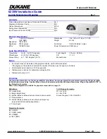
6. Select Group "
930
", if the value of each lamp mode is
set "1" as shown in the figure below, the white balance
adjustment is performed correctly, if "0", adjustment is
not done or failed. Readjust again.
Group-No. Advanced color mode:
Input Adjustment Mode (X, Y)
Data (Initial value)
982 - 1
Advanced color-Auto: PC Standard -X
310
982 - 2
Advanced color-Auto: PC Standard -Y
330
982 - 11
Advanced color-Auto: PC Real -X
315
982 - 12
Advanced color-Auto: PC Real -Y
340
982 - 21
Advanced color-Auto: PC Dynamic -X
300
982 - 22
Advanced color-Auto: PC Dynamic -Y
320
982 - 31
Advanced color-Auto: AV Standard -X
310
982 - 32
Advanced color-Auto: AV Standard -Y
330
982 - 41
Advanced color-Auto: AV Cinema -X
319
982 - 42
Advanced color-Auto: AV Cinema -Y
333
982 - 51
Advanced color-Auto: AV Dynamic -X
300
982 - 52
Advanced color-Auto: AV Dynamic -Y
320
983 - 1
Advanced color-Off: PC Standard -X
295
983 - 2
Advanced color-Off: PC Standard -Y
325
983 - 11
Advanced color-Off: PC Real -X
300
983 - 12
Advanced color-Off: PC Real -Y
330
983 - 21
Advanced color-Off: PC Dynamic -X
285
983 - 22
Advanced color-Off: PC Dynamic -Y
315
983 - 31
Advanced color-Off: AV Standard -X
300
983 - 32
Advanced color-Off: AV Standard -Y
330
983 - 41
Advanced color-Off: AV Cinema -X
313
983 - 42
Advanced color-Off: AV Cinema -Y
329
983 - 51
Advanced color-Off: AV Dynamic -X
295
983 - 52
Advanced color-Off: AV Dynamic -Y
325
Group-No.
Data value
Selected lamp mode
930 - 0
10
4-Lamps
930 - 1
10
2-Lamps 1 (Lamp 1,4 on)
930 - 2
10
2-Lamps 2 (Lamp 2,3 on)
* The lamp mode will change when the value of data is
set to 10.
Service mode
Input
Input 1
Image
Standard
Group
No.
Data
930
0
0
Ver
1.00
Gamma
4L
2L-1
2L-2
Ye Auto
1
1
1
Ye Off
1
1
1
* Ye Auto: Advanced color Auto
99: on changing the
lamp mode
11: present lamp mode
0: not done or failure
1: done
Содержание LC-XT6
Страница 192: ...192 IC Block Diagrams CXD3548 Gamma IC401 CXA7009 S H IC501 IC531 IC561 IC1501 IC1531 IC1561...
Страница 193: ...193 IC Block Diagrams FA5501 PFC IC1601 IC1651 HIN202 RS232C Driver IC3801...
Страница 195: ...195 IC Block Diagrams AX11005 Network IC8301 TE7783 I O Expander IC1801...
Страница 196: ...196 IC Block Diagrams...
Страница 204: ...SPL 8 LC XT6 Exploded Views M01 4 M01 5 Lens shift assembly M01 1 M01 3 M01 2...
Страница 209: ...SPL 13 LC XT6 Exploded Views Optical filter LC CS L19 Integrator assembly S06 L11 S06...
Страница 210: ...SPL 14 LC XT6 Exploded Views Condenser lens OUT assembly S06 L09 Integrator OUT PBS assembly S06 L12 S06 L20 S06 S06...
Страница 211: ...SPL 15 LC XT6 Exploded Views Relay lens OUT assembly L06 S06 S06...
Страница 212: ...SPL 16 LC XT6 Exploded Views L08 L07 In the Optical unit L15 L15 L05 L22 L14 L13 L21 L09 L10...
Страница 213: ...SPL 17 LC XT6 Exploded Views Optical filters assembly Mirror assembly L16 L16 L18 L17...
Страница 214: ...SPL 18 LC XT6 Exploded Views Labels W09 W07 W01 W01 W06 W08 W04 W04 W04 W03 W02 W05...
Страница 218: ...SPL 22 LC XT6 Mechanical Pats List...
Страница 258: ...SPL 62 LC XT6 Electrical Parts List...