


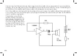


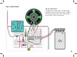


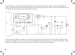


Capacitors are often used to
transfer sound frequency signals.
Here, we use a ceramic 100 nF
disc capacitor (labelled 104). This
amounts to just a 1000
th
of the
capacitance of the 100 µF e-cap.
A 100 nF capacitor is ideally suit
-
ed as a coupling capacitor at the
amplifier input.
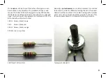
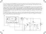
The 1 kΩ protective resistor is re
-
placed by a piece of wire because
after the successful initial test,
there is no longer a risk of a faulty
circuit. Later, you will insert the
main switch of the radio in this
place.
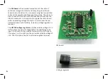
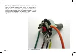
Pin 3 of the amplifier is now
additionally connected to GND.
This reduces distortions that
would otherwise occur by contact
resistances on the breadboard.
Pin 2 of the IC is the amplifier input, which will later be con
-
nected to the radio module via the capacitor. Touch the wire
of the capacitor. Again, you will hear low disturbing sounds
from the loudspeaker, e.g. a buzzing or humming. It originates
in the electrical wires and devices in the room, is received by
your body like an antenna and then amplified and made audi
-
ble. This simple buzz test is helpful to test the amplifier. It can
also be used to troubleshoot the completed radio later on.
19
Содержание RETRO RADIO
Страница 1: ......
Страница 14: ...14...
Страница 15: ...Step 2 Sound Generator Required components 10 k resistor brown black orange 15...
Страница 17: ...17...
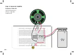
Страница 18: ...Step 3 Improved Amplifier Required components 100 nF disc capacitor 100 F e capacitor hook up wire 18...
Страница 20: ...20...
Страница 24: ...Step 5 Tuning Required components Hook up wire 24...
Страница 29: ...29...
Страница 35: ...Measured voltages 35...