


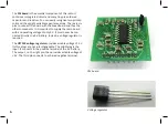

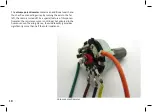


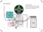


Initially, the eight legs of the IC have a slightly widened stance and must be aligned in parallel rows. This is best done with
pliers. Only now it is possible to insert the IC in the breadboard without effort. Be careful to mount the chip in the correct direc
-
tion. A notch at the left side marks pins 1 and 8.
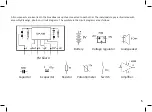
The assembly drawings show exactly what contacts have to be used. Carefully observe all the drawings. When you adhere to
them, everything will work just fine!
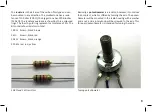
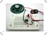
As most of the components will remain in the same position, it already makes sense to install a strain relief for the battery
wires at this stage to prevent the battery clip from damage. Remove the insulation from the ends of a piece of wire of approx.
2 cm and insert it in the breadboard as shown. Caution: Do not establish a conductive connection with the strain relief!
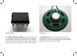
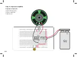
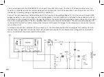
When you turn on the battery, you will
hear a low clicking noise from the loud-
speaker. Touch pin 2 or 3 with a piece of
bare wire or another conductive object.
Now a clicking or humming noise can be
heard. By touching the pins, you apply a
small signal voltage to the input.
13
Содержание RETRO RADIO
Страница 1: ......
Страница 14: ...14...
Страница 15: ...Step 2 Sound Generator Required components 10 k resistor brown black orange 15...
Страница 17: ...17...
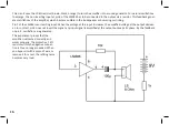
Страница 18: ...Step 3 Improved Amplifier Required components 100 nF disc capacitor 100 F e capacitor hook up wire 18...
Страница 20: ...20...
Страница 24: ...Step 5 Tuning Required components Hook up wire 24...
Страница 29: ...29...
Страница 35: ...Measured voltages 35...