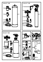
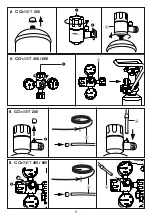

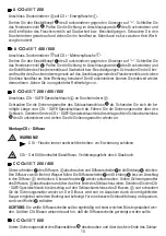


Push the CO
2
SAFE special hose onto the hose connection of the bubble counter
J
until the stop
and screw the locking nut tight again. Open the top screw cover of the bubble counter
J
, fill in
approximately two thirds water and close the cover again. Now loosen the cap nut at the top of
the bubble counter
J
, lead the CO
2
SAFE special hose through the cap nut and insert it in the
fitting on the top of the bubble counter
J
, Now unscrew the cap nut again. Push the silicon
adapter
R
halfway onto the CO
2
SAFE special hose. Now carefully push the hose connector onto
the diffuser
L
. The diffuser
L
is attached as close to the bed as possible with the suction cups.
The bubble counter
J
is attached to the aquarium from the outside. The check valve
K
has to be
on the bottom.
CAUTION:
The white diffuser plate should be cleaned regularly with a soft brush. Larger CO
2
bub-
bles indicate that the diffuser plate requires cleaning.
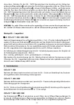
Assembly of the CO
2
long-term test
D
CO
2
SET
200 / 400 / 600
Fill the cover with aquarium water up to the mark (
≈
1 mL). Add 4 drops of indicator fluid
e
.
Push on the gasket and contrast ring
O
and mount the lower part on the hood and turn it. Position
the CO
2
long-term test in the aquarium at an easily visible location at medium height. For an exact
measurement of CO
2
content by means of the color scale, install the CO
2
long-term test on the
opposite side of the CO
2
diffuser.
The discoloration of the indicator fluid displays the CO
2
content of the aquarium water. The com-
parison with the color scale reveals the current CO
2
value:
blue = not enough, yellow/light green = too much, green/dark green = proper amount.
Please note: The correct display of the CO
2
content is displayed with a time delay of approximately
3 hours. The CO
2
long-term test should be refilled with new indicator solution after every change
of water or at the latest after 2 weeks.
6. Putting into operation
CO
2
SET
200
After all components are installed, the CO
2
supply can be opened on the adjustment knob of the
pressure regulator. Turn direction clockwise.
CO
2
SET
400 / 600
After all components are installed, the CO
2
supply can be opened on the main valve of the pressure
regulator. Turn direction counter clockwise.
The CO
2
supply is opened on the adjustment knob of the pressure regulator (turn direction clockwise)
until the manometer for the system pressure gauge
F
displays approximately 1.5 bar.
CO
2
SET
200 / 400 / 600
Open the fine control valve
D
on the pressure regulator until bubbles rise in the diffuser. It makes
sense to adjust the amount of bubbles to a low amount in the beginning. The amount can be increased
after a few hours until the right content is displayed in the CO
2
long-term test.
17